CAVE plugin
Introduction
See details in Introducing Accel VR chapter to understand how the CAVE works.
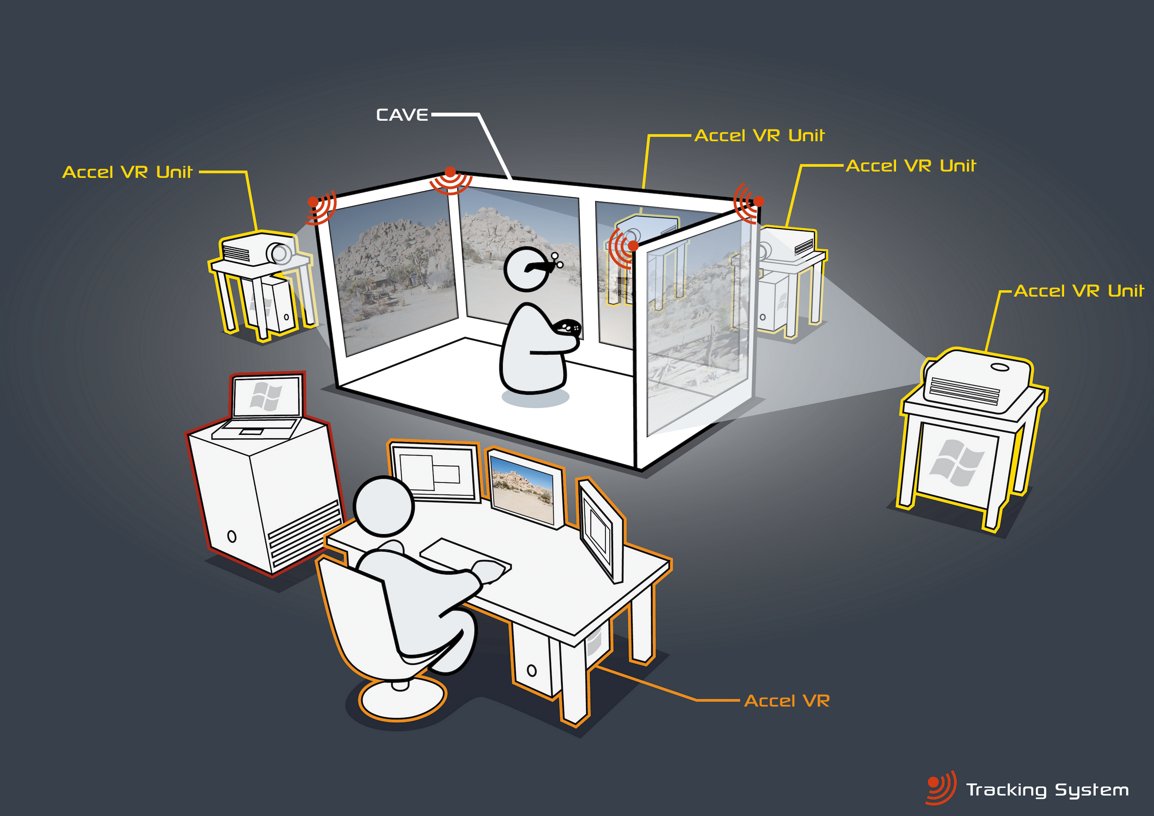
Figure 69 : Overview of a CAVE operating with Accel VR.
Calibration
Tracker calibration
For this step, you will need your tracking equipment. Follow the calibration instructions provided with the equipment. Calibrate the room and define the system origin in the tracker calibration software.
To greatly simplify things, define the origin of the tracking frame at the center of the room. This referential defines the origin and orientation of the shuttle frame. The square should be placed in such a way that the axes are collinear or orthogonal to the projection surface defined as the shuttle front window, in order to simplify the windows position measurement process greatly.

Figure 70 : Tracker calibration.
Tracker orientation
Select the Y UP or Z UP orientation for the tracking system according to the manufacturer’s documentation. If the tracking system does not use the Y UP convention by default, the input data will be translated into the tracking frame of reference.


Figure 71 : Y UP (left) and Z UP (right) orientations.
Head tracking orientation
Independently of the orientation convention used, the tracking system must be calibrated so that the X axis points toward the right.

Figure 72 : Step 7: Head tracking orientation.
Calibrating Projection Areas
The final step in preparation of the Accel VR system consists of calibrating the projection areas. This calibration must be performed on your virtual reality system whenever the image projected by one or more projectors is bigger than the corresponding screen or when its edges do not match edges of the screen. It sometimes happens that the projected image is not rectangular, displaying a keystone effect due to the position of the projector and display screen. This leads to distortion of the projected model.
The principle of this calibration is to reposition the corners of the projected image so that they match the corners of the intended screen.
You will need to know exactly where the origin of your tracking system is within your physical setup. If you cannot locate the point used by your tracking system as its origin, please go back and recalibrate your tracking system before proceeding.
The calibration follows these five steps:
Step 1: Launch Accel VR Pilot 2019.2 and all Accel VR Unit 2019.2.
Step 2: Click on this icon ![]() and then click on Import to import your *.kdr database from your PC. Select the database from the list and click Open.
and then click on Import to import your *.kdr database from your PC. Select the database from the list and click Open.
Step 3: In the product browser double click on your database thumbnail you just already imported.
Step 4: In the toolbar click on this icon  to display the rendering on your immersive system.
Step 5: In the toolbar again click on this icon ![]() to show Calibration manager dialog. Click on Start warping button.
to show Calibration manager dialog. Click on Start warping button.

Figure 73 : Windows warping box
A test pattern is projected by all render units in the system.

Figure 74 : Sample test pattern projected during calibration procedure for the projection areas.
On each unit, proceed as below:
Press the gamepad A button to configure the bottom edge. Using the joystick or the paddle (pixel precision) of the gamepad, reposition this edge so that its projection overlaps the bottom of the corresponding screen. Then press the B button on the gamepad to select the lower right corner and repeat the setting to place the corner so that its projection overlaps the bottom right of the corresponding screen.
Do this for all corners and edges that require adjustment in the order of the buttons shown in the table below.
| A | B | B | Y | Y | X | X | A |
| Lower edge | Lower right corner | Right edge | Upper right corner | Top edge | Upper left corner | Left edge | Lower left corner |

Figure 75 : Positioning the upper right corner with the joystick of the gamepad.
When an image is rendered, Accel VR will distort it in order to compensate for the keystone projection resulting from the position of the projector. The model’s normal proportions will be restored on the projection areas.
Areas outside of the test pattern will always be displayed in black in order to restrict the projection to the intended screen.
VRPN devices
Accel VR supports ART, VICON, and NaturalPoint tracking systems.
Accel VR Pilot 2019.2 establishes the link between the rendering units and the tracker, gamepads, etc. The connection is made via a local server.
Install the ART or VICON hardware according to the manufacturer’s recommendations. Accel VR Pilot 2019.2 must be linked to the machine on which the ART or VICON VRPN server is installed.
The important parameters to note concerning VRPN server are its IP address, the name of the main tracker (regarding glasses) and its index.
The VRPN server needs to receive information from the tracker (see manufacturer’s documentation).
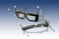
Figure 76 : 3D glasses
In order to use peripherals for navigating in the 3D scene (Logitech® gamepads, Xbox 360® controller for Windows®…), simply connect them to the computer running Accel VR Pilot 2019.2 and install the peripheral drivers. A space mouse may also be used too.

Figure 77 : SapceMouse® Pro
Proximity Warning
In an immersive system using walls, the observer is often unaware of the edges of the observation area and of the placement of the screens. To prevent the observer from running into the screens, a proximity warning is available.
Click ![]() to set the Proximity Warning.
to set the Proximity Warning.
The warning colors the display whenever an obstacle (the screen) is detected within a defined zone around the observer's head (Minimum distance and Maximum distance). This zone is defined in terms of the distance from the center of the observer's head.
You also can force its display (Force full) in a case of grid doesn't show up.

Figure 78 : Proximity warning window
