Projection Mapping plugin
Projection mapping is a projection technology used to turn objects, often irregularly shaped, into a display surface for video projection. These objects may be complex industrial landscapes, such as buildings, small indoor objects or theatrical stages.
This technique is used by artists and advertisers alike who can add extra dimensions, optical illusions, and notions of movement onto previously static objects.
Accel VR interacts with a projector through a rendering unit (Accel VR Unit 2019.2). Then the image fits to any object surface.
To match the projection with a real model, Accel VR uses projector information, the match between 2D points (placed with a gamepad by projection on the model) and 3D points chosen in Accel VR Pilot 2019.2 View to determine the camera position.
Click ![]() to show the projection mapping configuration window.
to show the projection mapping configuration window.
The following tabs will be used to select the settings:
- Projectors tab,
- Projection windows tab,
- Models tab.
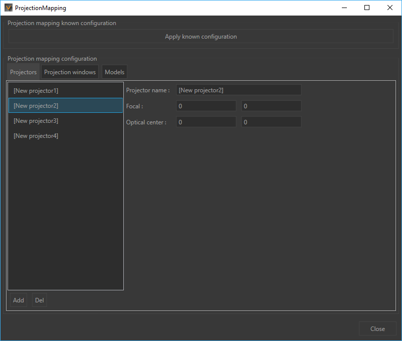
Figure 39 : Projection Mapping configuration example
Projectors tab
This tab allows you to add and configure projectors.
Click on Add button at the bottom of the editor, to simply add and configure a projector. You can also delete projectors from the list by clicking on Del button.
If projected image is too blurry and not centered, you can set its focal and its position with X,Y coordinates fields. Focal and Optical Center specifications can be given by the projector manufacturer. If you do not have them, go to the Projection Window tab to manually calibrate the projector(s).
Projection Windows tab
In this tab you can associate a projector to a window previously set in Advanced System Configuration section and calibrate its projection.
Association
To associate a window to a projector, it is necessary to proceed as follows:
- Click first on Associated window field on at the bottom left of the editor to select the window you want to associate.
- Click on Add button.
- Select the window in the list above.
- Associate the selected window with a projector.
Proceed like this for each window you want to associate with a projector.
Calibration
Calibrate projector button allows to calibrate your projector.
To retrieve the projector settings (Focal and Optical Center), it is recommended to calibrate each projector in 3-5 steps to correctly display the projected image on the surface.
Before starting the calibration steps, please connect first a gamepad (Xinput compatible) to the computer on which Accel VR Pilot 2019.2 is installed. Wait a few moments for the system to recognize it.
In the dedicated field, enter the number of steps you want to make, then click the Calibration steps button to start the calibration pass. The projector will then project a grid onto the desired surface. The calibration pass will be carried out using the calibration sheet glued to a rigid panel.
The calibration steps for one projector:
| Step 1 |
|
| n steps |
|
The calibration steps for n projectors:
Repeat operations 1 to 10 above for each projector.
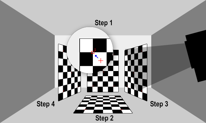
Figure 40 : Projector calibration example in 4 steps.
Models tab
Once Focal and Optical center have been found for each projector, you can now calibrate the projection onto the 3D model.
- On Models tab, click the Add a solving point button.
- In Accel VR Pilot 2019.2 View, place a red point with the mouse. The point must be easily identifiable. Select for example an intersection between two lines or an angle.
- Repeat 1-2 above to add 8 to 12 opposite red points.
- Then click on Solve position button to match the projection to the model.
You can delete the last solving point if you make a mistake during the association (Del last solving point). You can also reset all points by clicking the Reset solving points button.
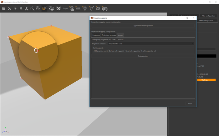
Figure 41 : Projection calibration example on a 3D model.
