Product Editor
Edit a product to modify which parts of the digital aspect mockup are used and how they are presented. You can do this by double-clicking on the product.
The product editor opens in a new tab.
At the top of the editor is a header bar listing the types of elements that can be edited.
Model
The default editing view for a product is the Model view. To switch to this view from a different view, click on the Model tab in the menu at the top of the editor.
A large preview of the model's default view is displayed. Below it, the model's filename, its unique identification code, and the date it was uploaded are listed.
At the top right of this box are the controls for the model and the model's default settings.
Updating the Model
You can update the model your product is based on. This is especially useful if changes have been made to the digital aspect mockup and you would like to update your product to include the modifications without losing the work you have already done on your product.
Click the  Update button to update the model used.
A box will open. In the Model drop-down list, the current model is selected. If you want to change the model used for this product, select a different model from the drop-down list.
Below the model selection is a zone listing the changes made last time the model was modified.
Tip
How to: Update a product's model
When a change is made to a model, a new KDR must be generated in Patchwork 3D Design or Patchwork 3D Engineering. The new KDR must be uploaded to Lumis 3D. If it is uploaded by someone other than you, that person will need to share the KDR with you before you can proceed.
From the file view, find your product. Double click on it to edit it.
This will open the editor in a new tab. The editor is already on the Model tab. At the top of this tab, click the
Update button to change the model used.A box will open. In the Model drop-down list, select the new KDR.
A list of changes will appear. At the top of the list, a warning will appear if the new KDR does not contain the same model as the old KDR. In the list of changes, each line begins with a symbol indicating the type of change found in the new KDR:
Symbol | Type of change |
|---|---|
- | Subtraction: This element from the old KDR was not found in the new KDR. It will be removed from your product. |
+ | Addition: This element was found in the new KDR but not in the original KDR. It will be added to your product. |
m | Modification: This element exists in the new and the old KDR, but is not the same. It will be changed in your product. |
Click Save to validate these changes.
Your parameters, configurations, clips, views, languages, and defaults will remain the same, unless items in them have been removed or changed. In this case, only those items will be modified. The rest of the items in the parameters, configurations, clips, views, languages, and defaults will remain the same.
Creating a Default Configuration
If your model has configuration options, you may want to set up a default configuration shown when you view the product.
Note
To set a default configuration, you will need at least one configuration preset. Configuration presets are imported from the KDR file or defined in the Configuration tab of this editor.
Click the  Default configuration preset button to select the default configuration preset for this product.
The Default configuration preset button opens the Default configuration box. At the top of the box, a preview of the current configuration is shown.
From the drop-down list, select a preset to use as the default. The preview at the top of the box is updated in real time.
Click the Save button to close the box and save your changes, or Cancel to close the box without saving.
Creating a Default View
If your model has multiple cameras, you may want to modify the default view of the product used when you open the product.
Click the  button to modify the default point of view.
This opens the Default view box. At the top of the box, a preview of the current default view is shown.
Choose the camera that will be used as a default viewpoint from the drop-down list.
When you make your selection, the preview at the top of the box is updated in real time.
Click the Save button to close the box and save your changes, or Cancel to close the box without saving.
Creating a Default Language
If your model has multiple languages, you may want to modify the default language of the product used when you open the product.
Click the  button to modify the default point of view.
This opens the Default language box. Choose the language that will be used as a default language from the drop-down list.
Click the Save button to close the box and save your changes, or Cancel to close the box without saving.
Views
Views make a product dynamic by allowing a scene to be viewed from different perspectives.
A view is a type of interaction paired with a model's camera position.
In the Views tab in the header bar at the top of the editor, you can pair cameras and interaction types.
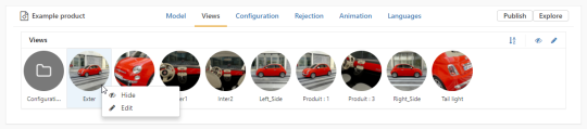
The header bar of Views tab allows you to:
Sort views alphabetically,
Hide camera's view(s),
Edit camera's view(s).
The cameras for the digital aspect mockup model are set up as cameras in Patchwork 3D Design or Patchwork 3D Engineering and saved in the KDR. They are automatically imported to the product. The camera groups are reproduced as folders in the Views tab.
Navigate into folders by clicking on their names as shown below.
To modify the interaction type assigned to a camera, double click on a round icon image. At the bottom of the editing window that opens, choose the desired interaction type.
There are three interaction types:
 Image: In an image, the camera is stationary. The viewer provides a picture of the digital aspect mockup from a preset perspective that cannot be modified in real time.
- VR Object: The digital aspect mockup can be turned interactively 360 degrees by clicking and dragging with the mouse. The camera position is not affected. The initial position is taken from the camera.
 Cube: Cubes are typically used to position the viewpoint inside the digital aspect mockup. The camera position is stationary, but the camera can be turned in any direction in real time to observe the interior space, such as the inside of a vehicle or a room, from all angles. Click and drag the mouse to change the direction. The initial position and orientation are taken from the camera.
The round icon image used for the view can be modified. At the top of the editing window that opens when you double click on the camera, click on  Upload custom thumbnail and choose the image you would like to use as an icon for this view.
Configuration
In the Configuration tab you will see the following common sections:
Presets are used to save a group of configuration options for quick access or to define a pack of options available together, but not separately.
Note
Lumis 3D distinguishes between configuration presets that were created in the KDR as configurations bookmarks, and configuration presets that you create. Configuration presets from the KDR cannot be modified or deleted.
Macros are used to save a partial group of configuration options for quick access or to define a pack of options available together. They allow you to impose a set of configuration options while letting you modify others.
Parameters, such as product color, allow you to change the value of a single configurable element. In this section, configuration parameters can be managed and organized.
The header bar of each section allows you to:
Add/delete configuration element(s) using respectively
 and
and  buttons. Configuration element(s) imported from the KDR cannot be deleted. To prevent them from being displayed when the product is viewed, modify their visibility.
Add/delete group(s) using respectively
 and buttons.
Sort configuration element(s) alphabetically using
 button.
Hide/show configuration element(s) using respectively
 and
and  buttons.
Edit configuration element(s) using
 button.
Navigate into subgroups.
Right-click on a configuration element displays the following actions:
 Edit opens the configuration element editing box. Only user-created configuration element can be edited. If the selected configuration element was imported from the digital aspect mockup, you can view its properties, but not change them.
 Hide the configuration element prevents the configuration element from being shown when the product is viewed. Click again on this icon to show the configuration element.
You can also select multiple configuration elements to edit them at the same time. Hold down the Shift or the Control key and select the desired elements.
Lumis 3D supports also drag and drop feature.
Configuration Presets and Macros
Tip
How to: Save a set of configuration options as a preset
To save a set of configuration options as a configuration preset in a product, click on the name of the product to open it. Click on the Configurations tab at the top of the page.
To create a configuration preset, click on the
New button in the top bar. This opens the Preset box.You can upload a custom thumbnail for this configuration preset by clicking on the
Upload custom thumbnail button below the round icon. If you do not upload a thumbnail, a cropped image of the preview will be used. Below the thumbnail, provide a name for this configuration preset. A preview of the preset is displayed. Below the preview, all of the options are listed as either drop-down menus if multiple values are available, or as checkboxes for options that can be enabled or disabled.Select a value for each option. As you modify the value for each option, the preview at the top of the box is updated in real time.
Click the Save button to close the box and save your changes, or Cancel to close the box without saving.
Tip
How to: Save a set of configuration options as a macro
To save a set of configuration options as a macro in a product, click on the name of the product to open it. Click on the Configurations tab at the top of the page.
To create a configuration preset, click on the
New button in the top bar. This opens the Macros box.You can upload a custom thumbnail for this macro by clicking on the
Upload custom thumbnail button below the round icon. If you do not upload a thumbnail, a cropped image of the preview will be used. Below the thumbnail, provide a name for this macro. A preview of the macro is displayed. Below the preview, all of the options are listed as either drop-down menus if multiple values are available, or as checkboxes for options that can be enabled or disabled.Select a value for at least one option. As you modify the value for each option, the preview at the top of the box is updated in real time.
Click the Save button to close the box and save your changes, or Cancel to close the box without saving.
Configuration Parameters and Their Values
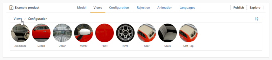
In the Configuration tab in the header bar at the top of the editor, you can also organize your configuration parameters into folders (groups) and provide a thumbnail for each of the options available in the product.
The configuration parameters, followed by the values for each parameter, are displayed below the configurations presets and macros.
The items in the current filter are listed just below the top bar. Drag an item onto a group name in order to place it in that group.
When you delete a group, the items in it are returned to the home folder. You can find them by clicking on the name of the home folder in the group path.
You can:
Place a parameter in a folder. Drag it from the list of parameters and drop it on the folder where it should be placed.
Remove a parameter from a folder. Click on the name of the folder to view its contents, then drag the parameter from the folder and drop it on the parent folder name in the list of folders. You can also drop it on the section title, Parameters, to remove it from all folders and place it at the root.
Change the order in which parameters or values are displayed. Click and drag a parameter or value to its new position in the list.
Change the thumbnail used for a parameter or for any of its values.
View configuration thumbnails in the explorer view.
Right-click on a parameter or value, and choose
Edit. This opens the editing window.Prevent the parameter from being shown when the product is viewed. Right-click on a parameter or value and choose
Hide. Repeat this action and choose Show to make a hidden parameter or value visible again. In the editor, hidden parameters and values are displayed grayed out.
You can also select multiple configuration parameters to modify their state at the same time. Hold down the Shift or the Control key and select the desired parameters.
Tip
How to: Change the order of configuration parameters / values
To change the order in which configuration options are listed, you will need to edit the product.
From the files view, double click on a product to open it.
Click on the Configuration tab.
Scroll down to the Parameters section.
Click and drag any parameter. Drop the parameter on top of any other parameter in the list to create a new order.
This same procedure will work for parameter values.
Tip
How to: Change the icon of an option
To change the icon that represents an option or an option folder when you view a product, you will need to edit the product.
From the files view, double click on a product to open it.
Click on the Configuration tab.
Scroll down to the Parameters section.
Right-click on the parameter and choose
Edit. This opens the editing box.Below the icon, click the
Upload custom thumbnail button to open the upload window. You can upload any image file.Navigate to find the image you want to use. Select it, then click Open to validate your choice.
Click the Save button to save changes and close the editing window.
Tip
How to: View configuration thumbnails in the explorer view
To view configuration thumbnails in explorer view.
From the files view, double click on a product to open it.
Click on the Configuration tab.
Scroll down to the Parameters section.
Right-click on the parameter and choose
Edit. This opens the editing box.Below the icon, check the Display explore button box.
Click the Save button to save changes and close the editing window.
In the product editor click on Explore button
At the bottom of the explorer view click
 Parameters
Select the parameter you want to explore its configuration thumbnails.
Click Explore button.
Tip
How to: Set up a KDR to create automatic thumbnails
Automatic thumbnails are generated by Lumis 3D based on the cameras present in the KDR.
Note
This procedure is case-sensitive. Pay attention to the use of capital and lowercase letters for elements that must have identical names.
In Patchwork 3D Design or Patchwork 3D Engineering, create only your configuration rules before creating cameras. Timeline animations must be created after creating cameras.
Create a camera group. Name it Configuration.
Within this group, create a camera for each configuration parameter for which you want a thumbnail to be created automatically. Place the camera in such a way that the element of interest is visible. Rename the camera so that its name and the name of the parameter's partition are identical. If you have a partition named "headrest", name the camera "headrest". If your partition is named "paint", you might have parameters "paint.blue" and "paint.red". In this case, name your camera "paint".
Create a second camera group. Name it Animation.
Within this group, create a camera for each timeline or clip for which you want a thumbnail to be created automatically. Place the camera in such a way that the animated element is visible. Rename the camera so that its name and the name of the timeline are identical.
Export the Patchwork 3D Design or Patchwork 3D Engineering product from Matter as a KDR via the menu Export > KDR. This KDR can be uploaded to Lumis 3D.
Thumbnails for views and for presets are created by Lumis 3D without any preparation on your part.
Tip
How to: Prevent a parameter from appearing in a product
To prevent a parameter from being shown when you view a product, you will need to edit the product.
From the files view, double click on a product to open it.
Click on the Configuration tab.
This hides the parameter in viewing and explore modes, whether the product is viewed on its own, as part of a scene, or in a product line review. In the product editor, the hidden parameter now appears grayed out in the list of parameters.
Right-click on the parameter you want to hide and select
Hide.Scroll down to the Parameters section.
To show the parameter, right-click on the parameter again and choose
Show.
Using Configuration Zones to Define Custom Parameters
Configuration parameters can also be created using predefined configuration zones and materials in KMT format.
The configuration zones must be defined in Patchwork 3D Design or Patchwork 3D Engineering prior to the creation of the KDR model.
Tip
How to: Set up a KDR to contain configuration zones
Open the P3D database of your digital aspect mockup in Patchwork 3D Design or Patchwork 3D Explorer. Make certain that you are in the Matter module.
Navigate to the Internal Libraries and then to the Material Library. Click on the
 icon to create a material to use as a zone marker.
Note
The class, name, and properties of this material will make no difference for the configuration zone. The default class (Standard) and default material settings are sufficient. However, it is best to chose a name that labels or describes the zone you are creating.
Note the name of this material. You will need it later to identify the material when creating the corresponding configuration parameter in Lumis 3D.
Assign the material by dragging and dropping it on all surfaces that will be affected when the material configuration will be changed.
Repeat steps 1-3 for other configuration zones in the same model.
Export your database as a KDR via the menu Product > Export > KDR.
Remember to save your database.
Create a new configuration parameter by clicking on the Add parameters button in the Parameters box. You will need to provide:
An optional thumbnail for the new material
A name for the new parameter
The type element used to define the parameter (Material is preselected.)
A selection of the specific element used to define the parameter, using the drop-down list. The affected surfaces will appear in red in the preview.
Tip
How to: Use a material to create a custom configuration parameter
Note
You must be Writer in the space where the product you want to edit is stored, and the Product and Scene Editors user module must be attributed to your account.
Note
The product you are editing must be based on a KDR that is set up to contain configuration zones.
When you use a material to create a custom configuration parameter, all surfaces to which that material is assigned become configurable. When viewing the product, you will be able to apply any materials listed as values of the custom parameter to these surfaces.
Double click on the product in which you want to add a custom configuration parameter. This will open the product editor.
Click on the Configurations tab at the top of the page.
Click on the
Add parameters button in the Parameters box. This box is the third box on the page, after the Presets and the Macros boxes.The Parameter window will open. In this window, provide the settings for the custom parameter:
If desired, you can add a thumbnail representing this parameter that will help you find and select it when viewing the product. To do so, click on the
 Upload custom thumbnail button below the round icon at the top of the window. Choose a thumbnail image from your computer or network and click Open.
Give your parameter a name in the Name field.
Select the type of element that will be used to create this parameter. In this case, the default choice, Material, is already selected.
Use the Select a material drop-down menu to select the material assigned to the configuration zone you are creating. The list contains the names of all materials used in the product, listed alphabetically. Once a material has been selected, the surfaces that make up the parameter's zone will appear in red in the preview.
Save the new parameter by clicking the Save button at the bottom of the window.
Once saved, the parameter will be added to the list of parameters in the parameter box. When selected, you can use the buttons at the top of the box to:
- Hide the parameter in this product
- Edit the parameter
- Delete the parameter
The parameter's values can be set in the box for this parameter, which appears at the end of the list of parameters on this page.
The  Import values button in the header of the parameter values box for your new parameter opens a new window. Navigate through the spaces you are a member of to select values for this parameter.
Parameter values can by any KMT files that you have access to.
You can select multiple KMT material files at a time by holding down the Shift or Control keys.
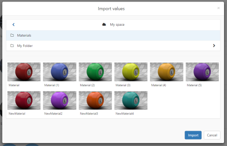
The Import values window allows you to navigate through your spaces to select KMT files as values for your parameter.
Tip
How to: Add values to a custom parameter
Note
You must be Writer in the space where the product you want to edit is stored, and the Product and Scene Editors user module must be attributed to your account.
Note
The product you are editing must be based on a KDR that is set up to contain configuration zones, and a custom parameter must already be created in the product.
Note
You must have access to KMT material files in one of the spaces of which you are a member.
A custom configuration parameter identifies all surfaces that should have the same aspect and lists the materials that can be used as values of this parameter. When viewing the product, you will be able to apply any materials listed as values of the custom parameter to the associated surfaces.
Double click on the product in which you want to add a custom configuration parameter. This will open the product editor.
Click on the Configurations tab at the top of the page. The custom parameters appear at the bottom of the list on this page.
Scroll down to the bottom to find the box labeled with the name of the parameter you want to add values to.
Click on the
Import values button in the header of the parameter values box. The Import values window will open.Use the Spaces zone at the top of the window to find the KMT material file or files you want to use as values. You can navigate through all of the spaces to which you have access and their folder structure.
Select a material by clicking on it, or select multiple materials using Shift-click or Control-click.
Click on the Import button at the bottom of the window to add the material as a value for this parameter.
Rejection
In the Rejection tab in the header bar at the top of the editor, certain combinations of configuration values can be forbidden for this product.
In this tab:
Consult the list of forbidden configuration combinations in the Rejected parameters box.
Consult the list of forbidden configuration combinations in the Rejected values box.
Use the
 Rejection explorer to mark combinations of configurations as forbidden or permitted.
Forbidden, or rejected, combinations are not available in the product.
Using rejected combinations allows the creation of product lines in which the available configuration values for one parameter depend on the value selected for a different parameter.
Rejected Parameters
Rejected Parameters allows you to forbid displaying a parameter compared to the value of another parameter.
An image for each forbidden configuration is displayed in the Rejected parameters box.
Hover the mouse over an image to view the combination that has been forbidden.
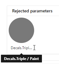
The combination of a triple stripes decals and a paint is forbidden (rejected) in this model.
Note
In the example above, if a user viewing the product selects a triple stripes decals, the paint color for the car will not be proposed and cannot be selected.
Click on a selected combination to:
- Delete the rejection for this combination. This combination will once again be allowed in the product.
Rejected Values
An image for each forbidden configuration is displayed in the Rejected values box.
Hover the mouse over an image to view the combination that has been forbidden.
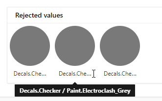
The combination of a decals with black, grey and espresso colors is forbidden (rejected) in this model.
Note
In the example above, the following paint colors: black, grey and espresso can't be proposed and cannot be selected with the checker decals.
Click on a selected combination to:
- Delete the rejection for this combination. This combination will once again be allowed in the product.
Rejection Explorer
The Rejection explorer helps you select the configuration combinations you want to reject from this product.
Click on the logo at the top right of the Rejected values box to open the Rejection explorer.
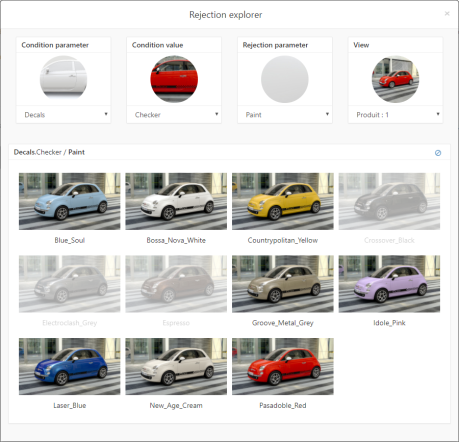
This window allows you to select one parameter and its value (the Condition parameter and value), and then to decide which values of a different parameter (the Rejection parameter and values) are allowed when the condition parameter and value are chosen in the product.
Use the drop-down menus to select:
The Condition parameter
The Condition value
The Rejection parameter
The View used for the visuals
Select the rejection value or values in order to:
 reject the selected values
 allow the selected values
Tip
How to: Reject combinations of configurations in a product
Note
You must be a writer or an administrator in a space to modify its contents.
Double click on a product to edit it.
Click on the Rejection tab at the top of the content area.
Click on the logo at the top right of the Rejected values box to open the Rejection explorer.
You are going to reject values of one configuration parameter (the Rejection parameter) when another parameter (the Condition parameter) has a specific value (the Condition value).
First, set the condition parameter and value by using the drop-down menus.
Then, select the Rejection parameter. The content zone in the lower part of the Rejection explorer window is now labeled with the name of the parameter you selected. This zone now contains a labeled image for each of the values of the parameter you selected.
In the View menu, choose one of the product views that allows you to see the differences between each of the values of the Rejection parameter.
Click on one of the labeled images to select that value.
Note
You can also select multiple values at the same time by holding down the Control key and clicking on additional values, or by holding down the Shift key and clicking on a second value to select all of the values between the two you clicked.
Click on the
logo at the top right of the content zone to reject the selected value or values.Close the Rejection explorer by clicking on the
 at the top right when you are finished.
Animations
Animation tab consists of two boxes, one for Animations and the other one for Timelines.
The animation clips and the timelines are listed in this tab if your KDR has these types of configuration.
By clicking on a clip this displays actions on the right in the top bar. These actions allow you to:
- Add a new group.
- Sort clips alphabetically.
 Prevent the clip from being available when the product is viewed. Click the visibility icon to change the availability:
A
 visible clip will be available in the product.
An
invisible clip will be excluded from the product.
- Edit the clip's settings:
Change the thumbnail associated with the clip by
deleting the existing thumbnail or uploading a new one.Allow the clip to be played as a video instead of a still picture by ticking Play Video checkbox.
You can select multiple animations to modify their state at the same time. Hold down the Shift or the Control key and select the desired clip or use drag and drop feature an item onto a group name in order to place it in that group.
Tip
How to: Make sure an animation will be visible when played
To ensure that animation will be visible when played, you can associate a view with a clip.
Select a clip by clicking on it.
Click the
Edit button that appears at the right in the top bar. This opens the Animation settings box.You can preview the clip and choose whether it Will use current point of view when played or whether it Will use specific point of view. Will use current point of view is selected by default. This allows the animation to play from any point of view for this model.
Select Will use current point of view to force the view to change when the animation is played. Then, use the drop-down lists to select the camera group and the camera that corresponds to the point of view you want to use.
Click the Save button to close the box and save your changes, or Cancel to close the box without saving.
Languages
From the Languages view, you can allow the names of the options that are displayed in the product to be modified. This is done by adding a language.
You can add multiple languages for the same product. If you have multiple language sets in a product, you can switch between languages from within the product viewer.
From this page you can add and modify languages containing translations of all parameters, values, configuration presets, and animation clips:
- Add language: This button next to the search box creates a new language.
You can click on an existing language to select it. This displays the item action options in the top bar that allow you to:
- Sort languages alphabetically.
- Import a CSV file containing translations for this language.
- Hide languages. Click the visibility icon to change the availability:
A
visible language will be available in the product.An
invisible language will be excluded from the product.
- Edit the clip's settings:
Change the thumbnail associated with the clip by
deleting the existing thumbnail or uploading a new one.Allow the clip to be played as a video instead of a still picture by ticking Play Video checkbox.
 Duplicate a language to which new translations can be added.
- Edit the language. Add translations for each text element in the language. You can also change the name that will be displayed in the
 drop-down language list when you view the product.
 - Delete the language.
Tip
How to: Edit a language
To edit the translations used for a language, click on the language you want to edit. The buttons allowing you to modify the language will appear at the right in the top bar.
Click on
Edit. A window will open. Next to each text element in the product, type the translation you would like to appear. If you leave a blank field, the original text will be used instead.Click Save to save your changes or Cancel to close this box without saving.
Editing the CSV Translation File
When you export a CSV file for a language, it will contain the following elements:
A list of all parameters, parameter values, configurations and clips in your product.
All of the existing translations for the language.
File Structure
The first line is a list of headings separated by commas. Do not modify the heading.
Each of the following lines corresponds to one item in your product. Its type is listed in capital letters, followed by its name in the original KDR file. Do not modify this information.
After the type and name, the translation into the language you are working on is listed. You can modify the text of an existing translation or add additional translations in this language.

Sample CSV file opened in a plain text editor.
Viewing as a Spreadsheet
In order to view the structure of the file more clearly, this file can be opened in a spreadsheet editor such as Microsoft Excel.
Note
Please see the instructions below in the section How to use a CSV translation file on opening and saving a CSV file in Microsoft Excel.
Every CSV translation file will contain the columns Type, Name. Do not modify the contents of these columns.
The third column is labeled with the name of the language you are editing. The existing translations are listed in this column.
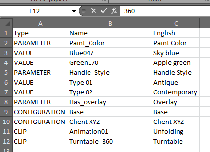
Sample CSV file imported into Microsoft Excel.
You can:
Modify the translation of an element. Find the element's row. Modify the text in the third column corresponding to the translation.
Note
If you leave a cell empty, the original text in the Name column will be displayed in the viewer for the item when this language is selected.
Tip
How to: Use a CSV translation file
From the product editor, use the header bar at the top of the editor to go to the Languages view.
Click on the language you want to edit. The buttons allowing you to modify the language will appear at the right in the top bar.
Click the
 Export button. This will download a CSV file named your_product_name-your_language_name.csv to your computer containing all of the translatable items in your product. If you have set up a default download location, it will be saved in that folder. If not, you will be asked to choose where to save the CSV file.
Open the CSV file. We suggest using a spreadsheet editor such as Microsoft Excel, but you can also use a basic plain text editor such as Notepad if you don't have a spreadsheet editor.
Note
The CSV file exported from Lumis 3D uses a comma separator. If you want to use Microsoft Excel to edit it, you will need to verify the separator used in CSV files in order to save your work. This must be done before you open Microsoft Excel.
In Microsoft Windows 7 or 8, open the Start menu, and then click Control Panel.
Click on the Clock, Language, and Region heading.
Click on Regional and Language Options.
Click the Formats tab, then click the Additional settings... at the bottom of the window.
Change the Decimal symbol to . (period).
Change the List separator to , (comma).
Click OK to close the Additional settings... window, then OK again to close the Regional and Language Options window.
This changes the separator that Microsoft Excel will look for in all files on your computer. You can undo this change by clicking the Reset button at the bottom of the Additional settings... window.
Note
The CSV file exported from Lumis 3D is encoded in UTF-8. If you want to edit it with Microsoft Excel and:
accents are used in either the original KDR files, or
any of your translations use accents
you will need to import the file instead of opening it.
Open Microsoft Excel. This will open a new spreadsheet.
Click on the Data ribbon.
Click on the From text import button in the first grouping of buttons on the left.
Select your CSV file and click Open.
In the Import Assistant window that opens:
select the radio button Delimited,
change the File origin drop-down list to 65001: Unicode (UTF-8).
Click Next.
In the Separators list, check Comma. Uncheck all other boxes.
Click Finish.
Insert the data in an Existing spreadsheet. If it is not already filled in, type =$A$1 in the text field.
Click OK.
Save your spreadsheet. Choose the file format CSV (comma delimited) (*.csv).
This file contains three columns: Type, Name, and a column for your language.
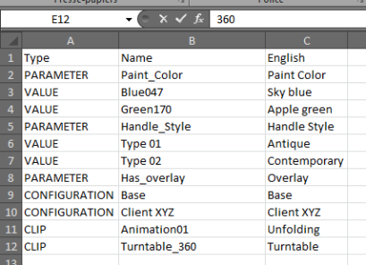
Sample CSV file imported into Microsoft Excel.
To modify the translation of an element, find the element's row. Modify the text in the third column.
Fill in a translation for every item in the translation columns. If you do not provide a translation, the text in the Name column will be displayed in the viewer.
Save your changes.
Return to the product's Languages view in Lumis 3D. Click on the language you want to edit. The buttons allowing you to modify the language will appear at the right in the top bar.
Click the Import button and select your modified CSV file.
This replaces all previous translations with the translations in the CSV file.