Standard Material
A Matter standard material allows you to simulate materials such as metal, wood, plastic, stone, paint, etc.
A standard material is designed to reproduce the characteristic behavior of a material immersed in a lighting environment. It is above all a visual simulation, in the field of perception.
The settings of a standard material are take into account the elements that define of the matter, i.e. the color and pattern, capacity to reflect or tint the environment, surface texture, transparency, and behavior during rendering by raytracing.
A standard material is broken down into a Diffuse coat, or layer, over which a Reflection layer is applied, each of which may be textured. The interaction between the two layers allows most materials to be simulated realistically.
The Matter module offers standard materials belonging to the following classes:
- Diffuse only: The material has color, pattern, and texture attributes, but does not reflect the environment. The reflection settings are not available.
- Diffuse and Reflection: The material has color, pattern, and texture attributes, and it reflects or tints the environment.
- Transparent Filter, or reflection layer only: The color of the material serves as a transparent filter. The material can be textured and reflects or tints the environment. The diffuse settings are not available.
Basic Principles
In order to give you an idea of the characteristic features of a standard material and to introduce the parameters associated in Matter, here is the breakdown of a slightly reflective fabric.
To replicate the appearance of a photorealistic material, the Matter module proceeds by layer:
- Diffuse: When created, a new material is slightly gray and has the appearance of perfectly smooth rubber.
- Color and pattern: The Color Map field is used to apply a pattern mimicking fabric fibers.
- Texture: In the Bump tab, the Bumpmap field encodes the surface texture used to simulate the unevenness of woven fabric. The depth of this unevenness is modulated by the Diffuse Depth setting.
- Reflection: The overlay of a reflection (type Diffuse and Reflection) without taking into account the unevenness of the texture on the reflective layer simulates a thin film of plastic on the fabric.
- Color: A reflective layer has a tendency to lighten the material.
- Texture: Final, to finish the material, enable and set the Reflection Depth in the Bump tab.
-
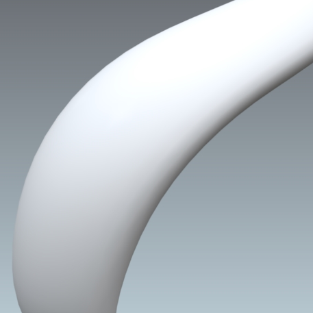
Figure 114 : Diffuse layer
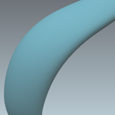
Figure 115 : Diffuse layer + color
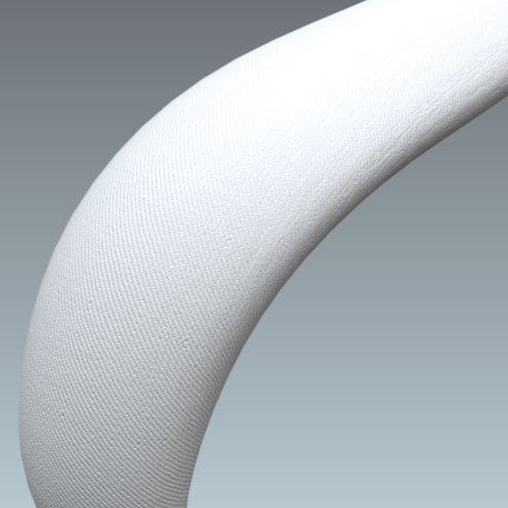
Figure 116 : Diffuse layer + diffuse texture
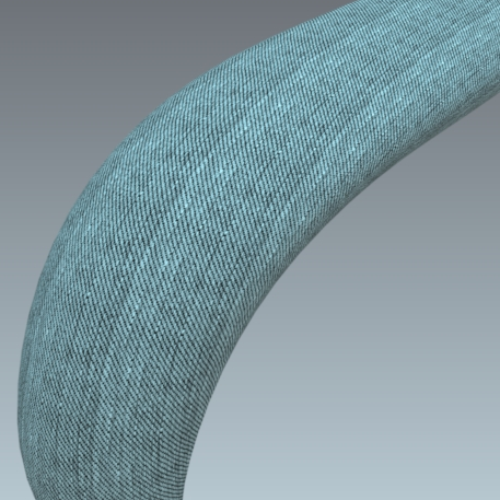
Figure 117 : Diffuse layer + color and pattern + diffuse texture
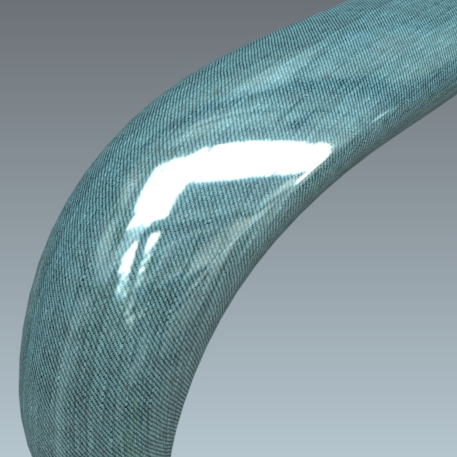
Figure 118 : Diffuse layer + color and pattern + diffuse texture + reflection
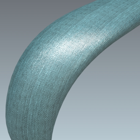
Figure 119 : Diffuse layer + color and pattern + diffuse texture + reflection + reflection texture
Diffuse
Light does not pass through a diffuse layer. Light is either absorbed, or returned to the eye of the observer. The Diffuse tab groups the settings related to this diffuse layer.
Diffuse Color
The color of the diffuse layer is influenced by several settings: the color Filter, the lighting environment conditions, the ambient color, and the illumination color, among others.
The color Filter setting corresponds to the color perceived when the material is lit by white light. As the material reacts like a filter, it reflects part of the light it receives. The perceived color of an object is thus greatly influenced by the lighting environment. If we consider that white light is made up in equal parts of green, red and blue (empirical computer model), then a black body absorbs all these components, a white body reflects them without alteration, a red body absorbs the green and blue, etc.
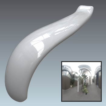
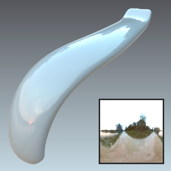
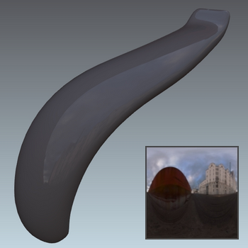
Figure 120 : Influence of the lighting environment conditions on the color of a material.
The creation of a new material should thus imperatively be performed in a neutral light environment, for example, the default environment in the Matter module.
The Intensity parameter allows you to amplify by a multiplication factor the effect of the lighting environment on the material.
The Ambient color parameter allows you to add a constant color. It is common practice to add a light gray to lighten a material. However, we would advise you to limit the amount of ambient light since a material of relatively dull appearance originates from a relatively dull environment.
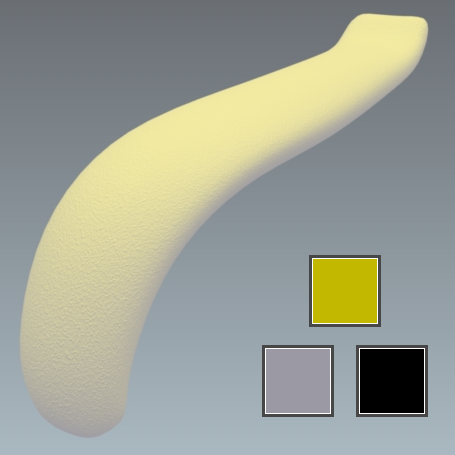
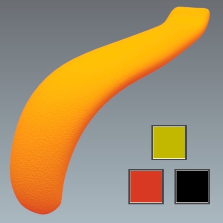
Figure 121 : The effect of an ambient color on the appearance of a yellow material. Left: gray ambient color. Right: red ambient color.
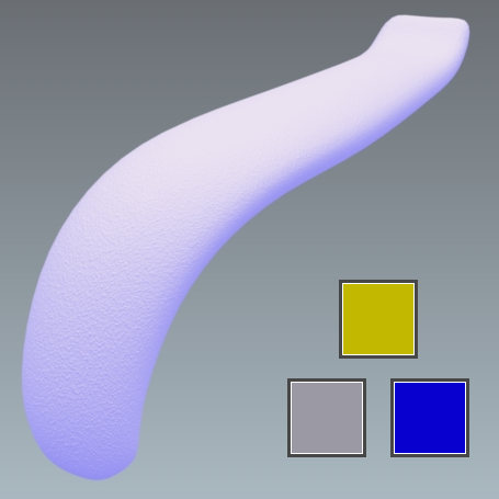
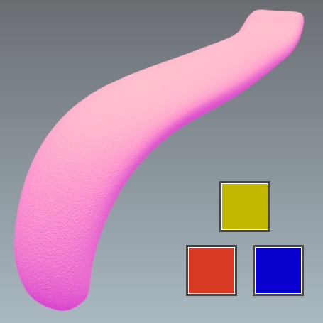
Figure 122 : The effect of an illumination color on the appearance of a yellow material. The same samples from the preceding figure are shown here with a blue illumination.
Color Map
Some materials have a pattern or motif that is created by repeating an image across the surfaces to which the material is assigned. The Color Map settings are used to assign, resize, and position the first instance of such an image.
Color maps are image
The texture dimensions are used by default for an image texture.
For a video texture, the longest edge of the format is scaled to one meter by default. The format's aspect ratio is respected.
Any texture used as a color map will repeat.
You will find in the accordion menu named Mapping the following parameters Allow repeat in U and Allow repeat in V that allow you to choose to repeat the texture in U and/or V.
By checking the Mirrored check box you can reflect the texture in U and/or V.
Transparency of the Diffuse Layer
The transparency of a standard diffuse-and-reflection material can be adjusted directly from the Materials Editor using the Opacity modulator:
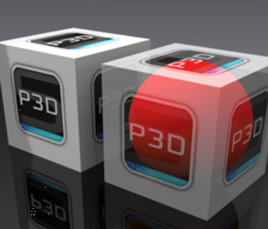
The Transparency accordion menu lets you use a texture for controlling the transparency of the material. The alpha layer contained in the images (PNG format) is used to define the transparency of the texture.
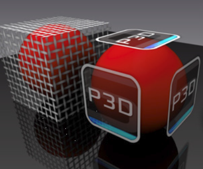
If the texture used as image alpha does not have an alpha layer (JPG image), it is the luminosity of the image that is used as the alpha layer. In this case, check Use color map transparency. The darkest colors correspond to the most transparent areas:
You will find in the accordion menu named Mapping the following parameters Allow repeat in U and Allow repeat in V that allow you to choose to repeat the texture in U and/or V.
By checking the Mirrored check box you can reflect the texture in U and/or V.
Filter According to View Angle
Some materials have a color that changes according to the angle of observation. This effect is implemented using a gradient ramp. Click on the ![]() Gradient Editor button from the accordion menu called Advanced in order to modify the gradient that is used.
Gradient Editor button from the accordion menu called Advanced in order to modify the gradient that is used.
Reflection
The reflection layer is an additive layer. This layer can be used in two ways. When combined with a diffuse layer (Diffuse and Reflection class standard materials), it helps to simulate materials that reflect the light of the environment such as metals, varnished woods, smooth or metallic paints, or opaque plastics.
This layer can also be used alone (Transparent Filter class standard materials) in order to simulate transparent materials. This transparency is obtained by removing the diffuse layer that blocks the light from passing through the material.
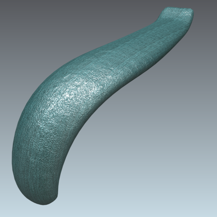
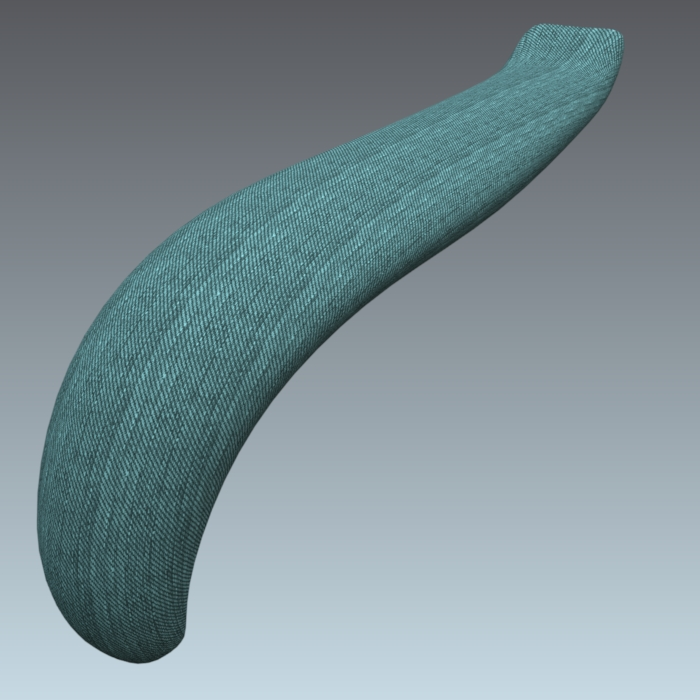
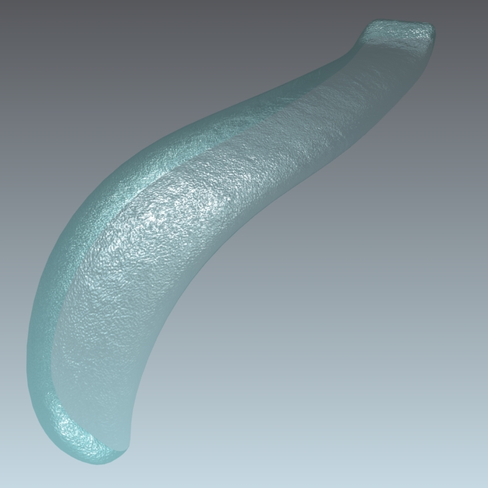
Figure 123 : Diffuse+Reflection (left) - Diffuse (center) = Transparent Filter (right)
Intensity
The Intensity setting allows you to adjust the amount of reflection emitted by the material. The Intensity value varies in principle between 0 and 1, but a higher value makes it possible to counterbalance a rather dull lighting environment.
A perfect mirror appearance is obtained with the value 1. Even though the color filter parameter enables you to attenuate the reflection, we would recommend modifying the Intensity value, since it gives access to a more precise adjustment without any risk of coloration.
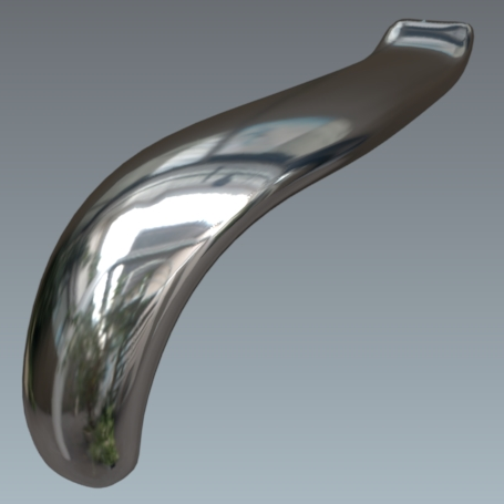
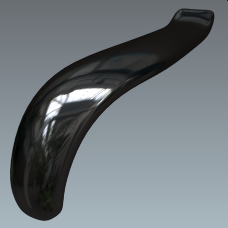
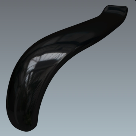
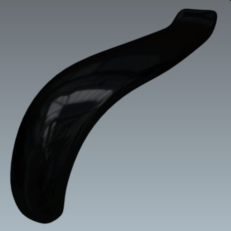
Figure 124 : Variation in the attenuation of the reflection using the Intensity setting, set to values from 1 to 0.005.
Color Filter
The color Filter setting in the Reflection Color zone is used to tint the reflection. This coloration reproduces the behavior of metals and of certain paints. This parameter may optionally serve to gradually attenuate the effect of the reflection by selecting a filter ranging from white to black.
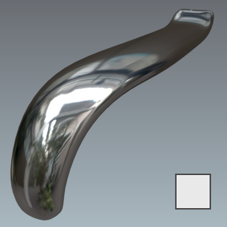

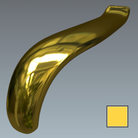
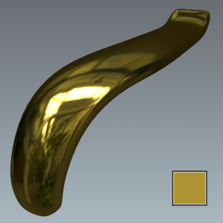
Figure 125 : Variation in the Filter parameter.
The Fresnel is an optical effect. The greater the oblique angle at which a glossy surface is observed, the less visible will be the color of the surface, which forms a white reflection.
In the case of a glossy transparent material, the Fresnel will make the surface increasingly opaque the more the viewing angle is reduced.
If no change appears in the rendering, return into Shaper in the lighting module to verify that none of the boxes of the lighting cube dialog box are checked.
To produce a material of motor vehicle bodywork paint type, it is necessary to enable the Fresnel effect.
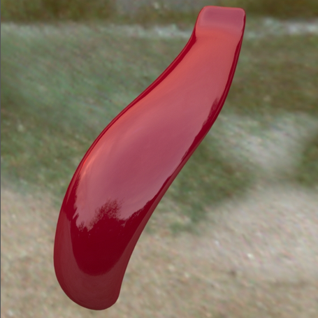
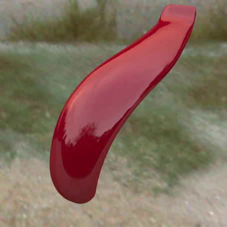
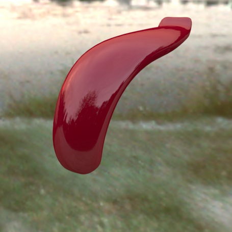
Figure 126 : Without the Fresnel Effect: no colorless reflection appears when the product is viewed at a sharp angle.
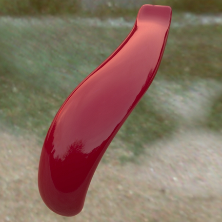
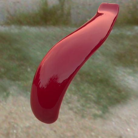
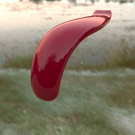
Figure 127 : With the Fresnel Effect (refraction index = 1.518).
Preset parameters let you allocate the refraction index and extinction coefficient values corresponding to common materials such as aluminum, silver, chrome, copper, gold, etc. Custom presets can be added to this list from the User Presets tab in the Patchwork 3D DesignSettings.
The extinction coefficient is a feature specific to the metals; this parameter can be left at 0 in the other cases.
The Fresnel also applies to transparent materials.
Specular Map
You can also restrict per pixel the intensity of the specular reflection of a material by using specular texture modulation (STM). This gray scale texture encodes the attenuation factor for each pixel the attenuation factor to be applied to the reflection (reflection = STM * specular).
A value of 255 encodes a maximum reflection and 1 encodes a virtual absence of reflection. This approach makes it possible, for example, to simply simulate embroidered fabrics. The value 255 is attributed to the pixels corresponding to the embroidery pattern, and the value 1 to the fabric.
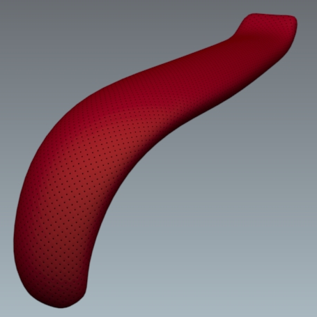
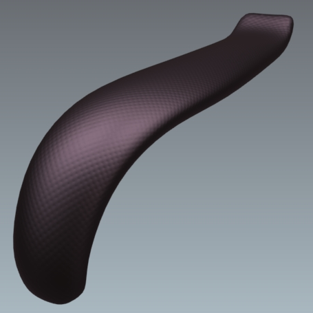
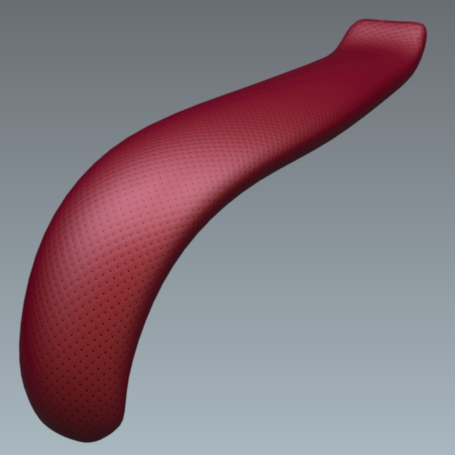
Figure 128 : Reflection filtering without a specular map. From left to right: diffuse layer, reflection layer without a modulation image, and result with a lightening effect.

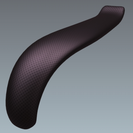
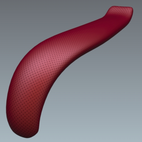
Figure 129 : Reflection filtering with a modulation image. From left to right: diffuse layer, reflection layer with a specular map, and result with a filtered lightening effect.
You will find in the accordion menu named Mapping the following parameters Allow repeat in U and Allow repeat in V that allow you to choose to repeat the texture in U and/or V.
By checking the Mirrored check box you can reflect the texture in U and/or V.
Roughness
The reflection of a frosted or brushed material is always hazy and coarse, the details disappear, and the reflection runs and spreads over the surface of the material. Only the silhouettes of the reflected objects are still apparent. This diffusion of the reflection on the surface of the material is due to a very perturbed surface state. The Roughness parameter replicates this behavior.
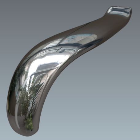
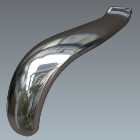
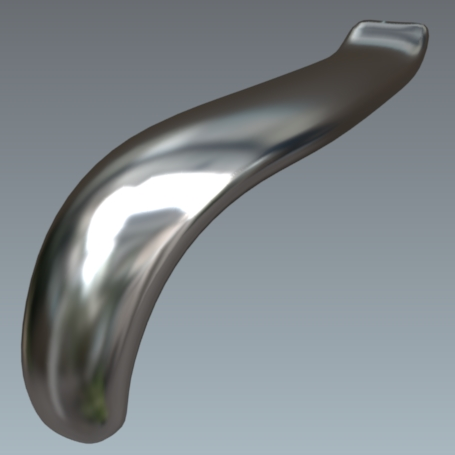
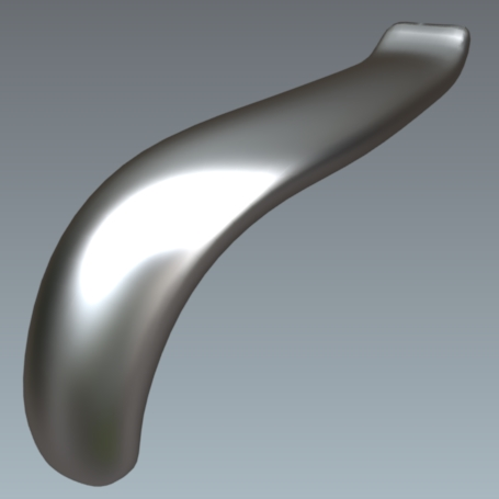
Figure 130 : Variation of the Roughness of the reflection, set to values from 0 to 6.
The roughness describes the surface irregularities that cause differentiated diffusion of light. The reflected light varies randomly depending on the roughness of the surface. This change the direction of the light without affecting its intensity because it remains constant. The rougher surface have a larger and variable highlights than smooth surfaces that have concentrated specular reflections. Smooth surfaces may look brighter with the same amount of reflected light.
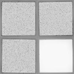
The Roughness map is a grayscale texture where the black corresponds to a roughness of 0 (smooth) and white corresponds to a roughness value of the material.
In the Roughness map accordion section check Enable and then click on the None button to load the texture that will serve for the roughness or glossiness of the material.
On the other hand, the Gloss map is a grayscale texture where the black corresponds to ta value of the material roughness and the white corresponds to a roughness of 0 (smooth).
|
|
|
Figure 131 : Gloss map example |
|
|
|
|
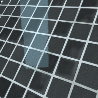
Figure 132 : Rendering without a gloss map |
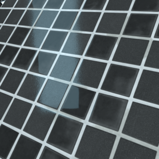
Figure 133 : Rendering with a gloss map |
You will find in the accordion menu named Mapping the following parameters Allow repeat in U and Allow repeat in V that allow you to choose to repeat the texture in U and/or V.
By checking the Mirrored check box you can reflect the texture in U and/or V.
Diffuse Filter
In the case of a standard material of the Diffuse and Reflection class, the additive aspect of the reflection layer tends to lighten the material when the reflection layer is superimposed.
This standard material class has a Diffuse filter to compensate for this lightening while conserving the original color.
A diffuse-free material (chromium, gold, steel, aluminum, etc.) is obtained by using the black filter.
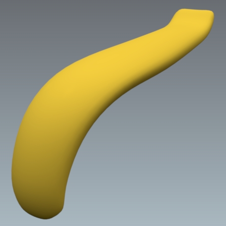
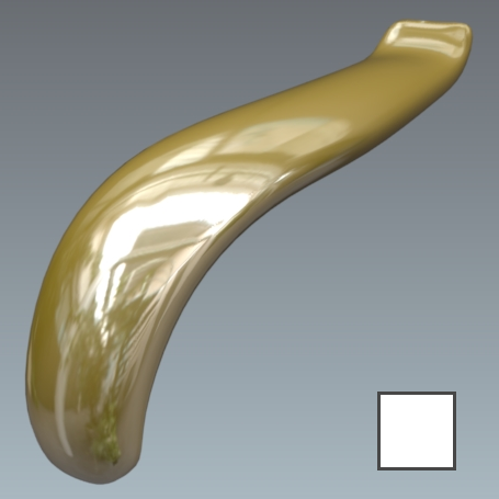
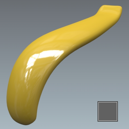
Figure 134 : Correcting lightening of a Diffuse and Reflection class standard material. From left to right: diffuse layer; diffuse layer + reflection layer without a filter (white filter); diffuse layer + reflection layer with a gray filter.
Transparent Filter
A standard material of the Transparent Filter class has a Trans. Filter setting, which plays the role of the transparent filter. This corresponds to the color of the transparent material.
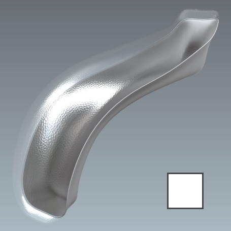
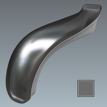

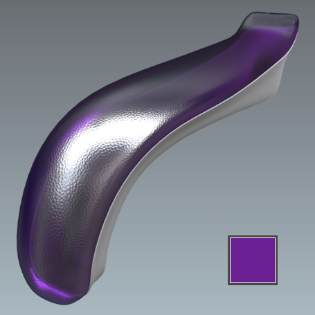
Figure 135 : Variation in the Trans. Filter setting of a Transparent Filter class standard material.
Bump
In the Bump tab, the parameter Diffuse depth adjusts the depth of the unevenness encoded in the Bumpmap. It is a surface state roughness, i.e. not very deep. From a geometrical viewpoint, the surface is not altered, and remains perfectly smooth.
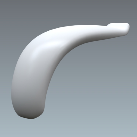
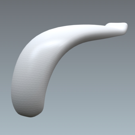
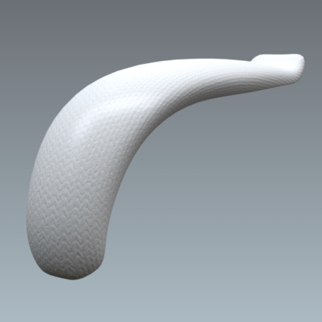
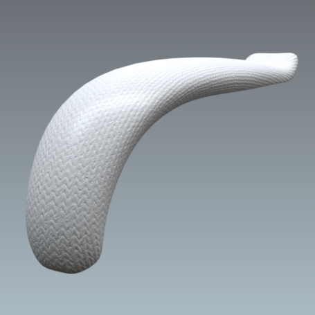
Figure 136 : Variation in the Diffuse Depth setting with values from 0 to 6.
The parameter Reflection depth adjusts the depth of the hollows and bumps encoded in the Bumpmap. The grain levels of the diffuse and reflection coats have been dissociated to produce thin reflective films.
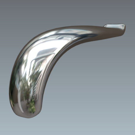
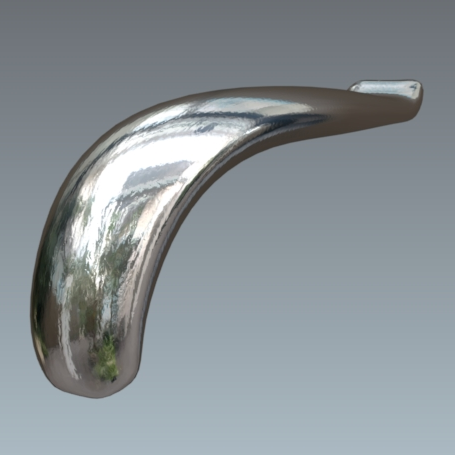
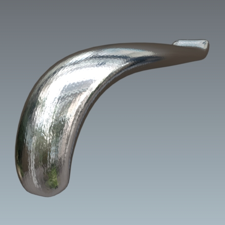
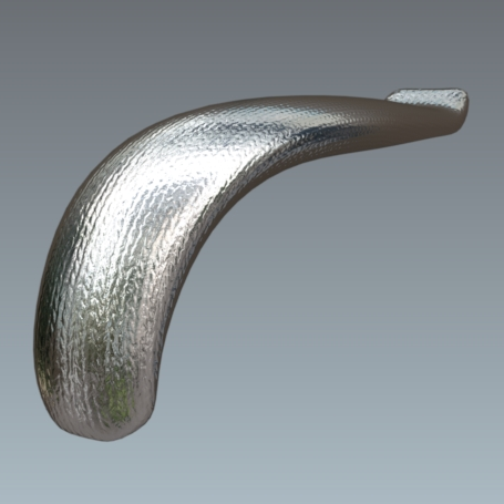
Figure 137 : Variation in the Reflection Depth setting with values from 0 to 3.
Enhanced Relief
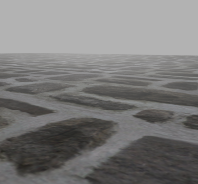
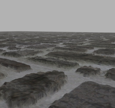
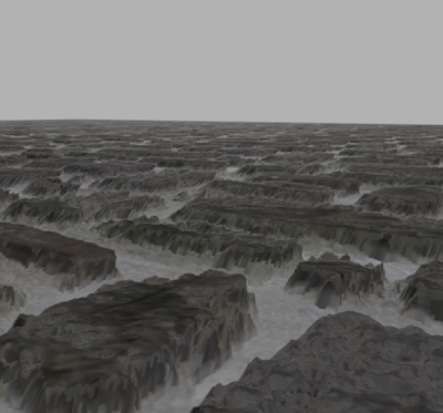
Figure 138 : Variation in the Relief depth setting with values from 0 to 10.
Standard materials using a height map can be rendered with textural relief that is even more realistic. This option offers an enhanced perception of depth thanks to the way it handles parallax.
The use of enhanced relief is best suited to contexts where a standard material uses a texture that requires more visual depth than that which can be rendered using diffuse depth and reflection depth.
The relief setting provides a rendering which, while robustly real-time, requires more time to calculate. It is therefore recommended to use this option where appropriate, without overloading a scene.
Enabling Enhanced Relief
Enable enhanced relief in the Bump tab of the Materials editor for a standard material:
- Tick the Relief checkbox in the Depth section and provide a value for the depth.
- Assign a texture as a Bump Map.
- Make sure that the bump map's Usage is Height map.
Disabling one of these elements will also disable the enhanced relief.
Settings
The settings for this type of render are found in the Bump tab of the Materials editor:
| Setting | Description |
|---|---|
| Relief depth |
The depth defines the distance between the white and the black zones of the height map. The white zones are aligned on the mesh of the surface. Because the perceived depth of the map's black zones is set using this parameter, the height map should make use of the full range of elevation available, from white to black. When this is not possible, make sure that the map's maximum elevation will be aligned with the modeled surface, that is, that it is represented in white on the height map. A negative value will invert the depth of the texture: depth is rendered as rising from the surface instead of as incisions carved into the surface. While possible, this rendering is not optimal and is not recommended.
Values between 0 and 10 are usually sufficient. Using values that are too high can create visual deformations when viewing surfaces at low angles or when viewing curved surfaces.
|
| Bump map |
A height map is required. This map is a black and white texture that is assigned to the material as a bump map. The texture to be used as a height map can be square or rectangular. The height and the width of the texture in pixels must both be powers of two.
Although Patchwork 3D Design will resize height maps whose dimensions are not useable, choosing textures with dimensions that are powers of two is highly recommended in order to preserve the particularities of the height map.
|
| Usage of the bump map |
The usage of the bump map as a height map is required. Enhanced relief is not compatible with bump maps used as normal maps. |
| Dimensions and Transformation of the bump map | These settings are modifiable as normal in order to adjust the dimensions, the orientation, and the position of the height map on the surface. |
You will find in the accordion menu named Mapping the following parameters Allow repeat in U and Allow repeat in V that allow you to choose to repeat the texture in U and/or V.
By checking the Mirrored check box you can reflect the texture in U and/or V.
Label
The label Properties apply when a material is used as a label.
You will find in the accordion menu named Mapping the following parameters Allow repeat in U and Allow repeat in V that allow you to choose to repeat the texture in U and/or V.
By checking the Mirrored check box you can reflect the texture in U and/or V.
Raytracing
Each material behaves differently during a rendering by raytracing. The Raytracing tab gives you control over the settings for this behavior.
