Tools tab
Notice
All the features described below may not be present in your software edition: Community, Premium, Essential, or Enterprise.
The Tools tab lists the manipulators used by your device according to the license you purchased.

The interest point tool allows you to point an area that you need to focus on like a pointer during a slide presentation.
By expanding the menu  you can directly select the area you want to draw the audience's attention using the eyedropper
  , or delete the point of interest with
  . You can also adjust its Size and Opacity from this icon
  .
.

The Measuring Tools shows the distance between two points that you have chosen. This distance between these two points may thus be represented visually in the active view.
With the accordion menu you can directly:
measure a length between two points
calculate an angle
Measure a length
Click on the eyedropper
and select your starting point (Point A) in the viewport.Then click on the endpoint (Point B) to measure the length between the two points
The result is displayed directly in the viewport or in the field named Length AB.
Note
If you want to measure another length, just click the eyedropper again to restart the procedure described above.
Calculate angles
The option Compute angle allows you to display the value of an angle between two segments. To measure an angle, do the following:
Check Compute angle, the fields Length BC and Angle ABC appear.
Click on the eyedropper
and select the starting point (Point A) in the viewport.Then click on the intermediate point (Point B) to measure the length between the first two points (Length AB).
Click on the endpoint (Point C) to measure the length between the intermediate point and the endpoint. You automatically have the length of the second segment (Length BC) and the value of that angle (Angle ABC ).
Tip
Repeat the procedure from point 2 each time you want to measure an angle.
The Measurement tools management tool gives you the following information:
the coordinates of each point
the length of each segment
the value of the Angle ABC

Turntables simulate the rotation of one or more products on a turntable. For example, they make it possible to visually compare several configurations of the same product from different angles.
In the accordion menu you can directly control turntables by selecting the rotation direction (clockwise and counterclockwise) or pausing the animation. It is also possible to change the rotation speed with the dedicated slider Speed (rpm).
From this icon you can adjust the Product Spacing, adjust the quantities + and - of the products you want to add to the scene, and view the turntable(s) by clicking on Start.
Note
The rotation is performed only along the axis of the rotation which is specific to the product.

The snapshot tool allows you to snapshot a scene in VR according to the operator's point of view.
You can directly capture the viewport by clicking on the Snapshot button in the accordion menu .
Click this icon to select the folder in which the snapshots will be saved or to set the dimensions of the snapshots while the Snapshot FOV sets the point of view angle.

The clipping planes tool allows you to section the object of the scene in a pre-designated plane to see its interior. Active clipping planes are visible in all open View and will clip through all products.
With the accordion menu you can directly:
show (Active)
 or hide
  the clipping planes.
move
 clipping plane(s) depending on the chosen X, Y, Z axis.
rotate
 clipping plane(s) depending on the chosen X, Y, Z axis.
Click on this icon if you need to refine the settings of the clipping planes: grid steps, color, thickness, etc...
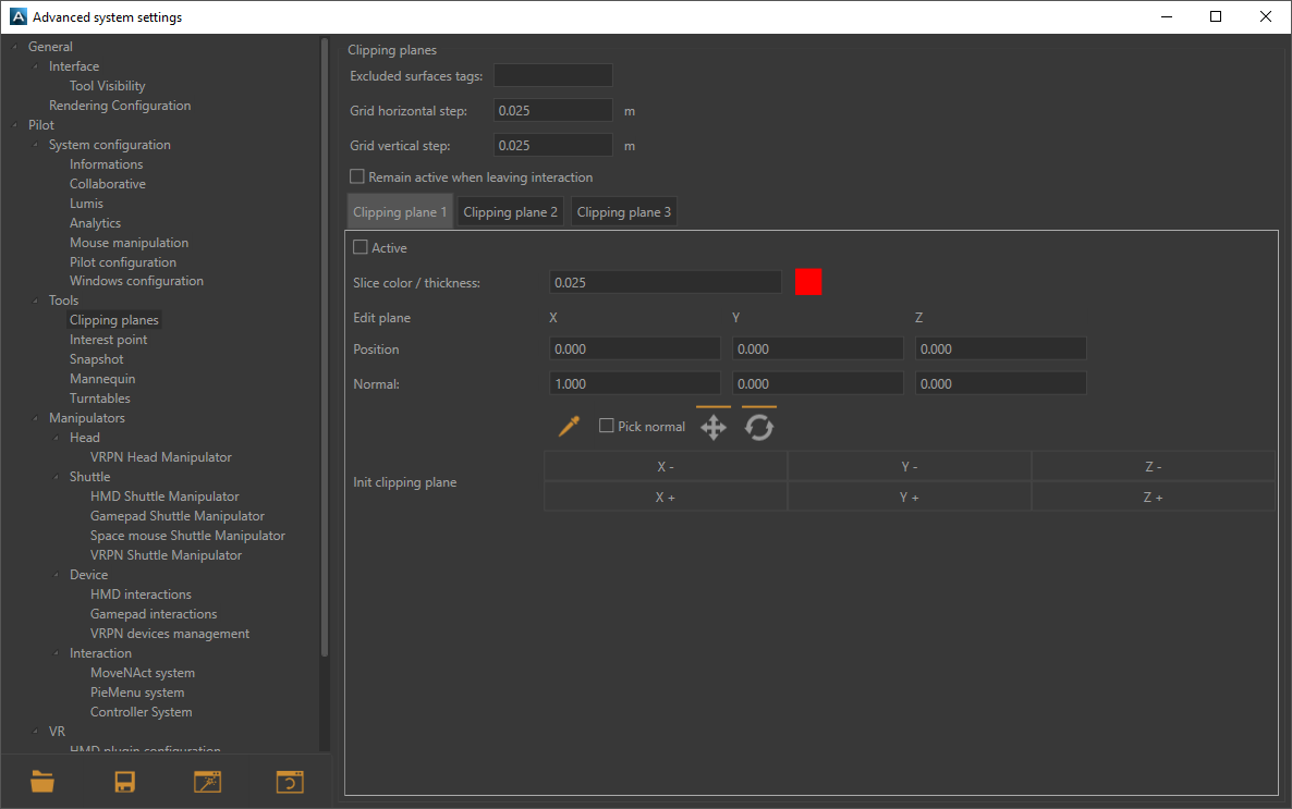
Clipping Planes Advanced Settings Window.
Tip
Tags used in Patchwork 3D to exclude surfaces from the clipping planes must be titled the same way in Accel VR.
For more information, please refer to the Clipping planes (Editor) chapter in the Patchwork 3D documentation. Accel VR excludes by default the label with the title NoClip.
Note
Clipping planes are positioned in the world. Consequently, moving a product in the world will not move the plane. The position at which the plane clips the product will be modified.
You can set the horizontal spacing (Grid horizontal step) and the vertical of the grid (Grid vertical step) by entering values or using the up and down arrows on the keyboard.
Accel VR Pilot allows you to manage and display three clipping planes simultaneously.
Check Remain active when leaving interaction if you plan to combine the use of clipping planes with other interactions.
Tip
Make sure the Active box is checked to display a clipping plane.
However, you can exclude certain surfaces from the clipping planes by entering in the Excluded surfaces tags field the surface tag you want to exclude. If you have several surfaces to exclude use semicolons between each tag.
You can choose the color of the slicing-edge and modify the Slice thickness of the line by entering a numerical value, or by using the up and down arrows of the keyboard.
Selects a point of the surface in which the clipping plane passes through the surface that you want to section.
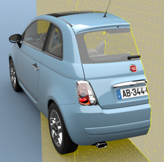 Clipping planes example with 1 section | 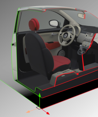 Clipping planes example with 2 sections |

Tip
By default, the Links tool is not visible in the tab Tools from the Accel VR side panel. To make it appear, just click this icon  and follow this path Advanced system settings > General > Interface > Tool Visibility.
The Links tool allows you to link a tracker to one or more products. With this feature, you can imagine moving a product naturally according to the movements of your members for example.
You can select and configure the trackers listed in the Trackers box by expanding the accordion menu or by clicking on this icon .
Follow these steps to link a tracker to one or more products.
In the Links window, select the tracker from the list.
Then with the eyedropper
pick the reference point onto the product. This allows you to link the tracker to the product.
Note
To link a tracker to multiple products, restart at step 1 (describes above) by using the same tracker but by selecting a different product at step 2.
At any time you can break the link from the tracker to the product by clicking on this icon . Use the translation gizmos  and rotation
  if you need to change the reference position of your link.
Warning
Only available with a CAD Tools license option.
The Product Mesh Collider is used to display the intersections between products when they collide.
When the Include avatars in the A group box is ticked, the avatars (head, controllers, hands) are included in group A for the calculation of collisions.
When the Product Mesh Collider is activated (Activate) you can set the collision behavior. The algorithm used requires dividing the products of the scene into two groups A and B. For each product, the collisions with all the products of the other group will be calculated. Collisions between two products of the same group are not calculated.
By selecting Surfaces you will visualize the intersection of the surfaces of product A with the surfaces of product B, an intersection line of the color of your choice appears.
By selecting Volumes you will visualize the intersection of the surfaces of product A within the volumes of product B, a plane of the color of your choice appears.
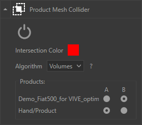
Here the Product Mesh Collider is set up with a red intersection using the intersection algorithm Volumes.
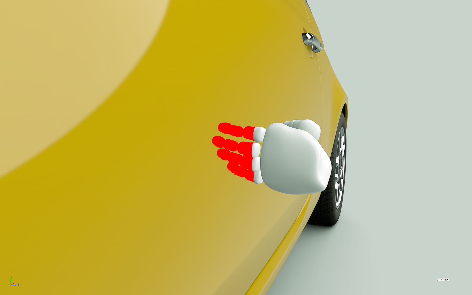
Here's the result.