Importing 3D CAD Models
In the Shaper interface, CAD models are imported using the menu Model > Import or File > Import in a new database. To import a model, select the desired file format, and then select your file using the browser. A status bar will appear, indicating the progress of this import.
The following file formats are available:
FBX (*.fbx)
DXF (*.dxf)
Wavefront OBJ (*.obj)
3DS (*.3ds)
STL (*.stl / *.sta)
Parasolid (*.x_t / *.x_b)
Parasolid IGES (*.iges / *.igs)
Solid Edge (Assembly= *.asm ) / (Part= *.par)
SAT (*.sat / *.sab)
XML (*.xml)
STEP (*.step / *.stp)
Creo, PRO Engineer (*.prt / *.asm)
Catia V4 (*.model / *.exp)
Catia V5 (*.CATPart. /*.CATProduct)
CATProduct V2 (*.CATProduct)
Wire file
Wire folder
NX (*.prt)
SolidWorks (Assembly= *.sldasm) / (Part=*.sldprt)
Lumiscaphe P3DXml (*.xml)
The import compatibilities in 2023 X6 are as follows:
Source | Format | Support in Patchwork 3D |
|---|---|---|
3D XML | .3dxml | From 4.0 up to 4.3 |
Autocad DXF | .dxf | Up to 2023 |
Siemens NX | .prt | From 11 up to NX 2206 |
Siemens NX Direct 5 | .prt | From NX up to NX 2206 |
SolidWorks | .sldasm, .sldprt | From 98 up to 2022 |
Autodesk Maya | .fbx | Up to 2020.3 |
Autodesk 3ds Max | .fbx | Up to 2020.3 |
Acis | .sat | R1 - 2022 1.0 |
Parasolid | .x_t, .x_b | Up to 35.0 |
Alias | .Wire | Up to 2023 |
SolidEdge | .asm, .par, .psm, .x_t | From V18 up to SE 2022 (with Parasolid export) |
Creo Pro/Engineer | .asm, .asm.*, .prt, .prt.* | From PRO/E Release 16 up to Creo 9.0 |
Catia V4 | .model, .exp | From 4.1.9 up to 4.2.4 |
Catia V5 | .CATPart, .CATProduct | From V5 R8 up to V5-6 R2022 |
Catia V6 | .CATPart, .CATProduct | Up to V6 R2022x |
Rhino | .3dm | From 2 up to 7 |
OBJ | .obj | All versions |
STL | .stl | All versions |
3DS | .3ds | All versions |
Step | .stp, .step, .stpZ, .stpx | AP203, AP214, AP242 versions |
IFC | .ifc, .ifczip | IFC2x3, IFC4 |
IGES | .iges, .igs | Up to 5.3 |
Based on the format of the file you would like to import, it is recommended to use the first possible line in the following table:
From | To | Importer to Use |
|---|---|---|
Catia, Acis, NX, SolidWorks, Parasolid, software supporting FBX | Patchwork 3D | Direct interoperability (for example, use the NX importer for NX files) |
software supporting STEP | Patchwork 3D | STEP |
software supporting IGES | Patchwork 3D | IGES |
software supporting OBJ | Patchwork 3D | OBJ |
any other software | Patchwork 3D | DXF, STL |
Patchwork 3D uses two 3D modeling engines to import file formats storing geometry elements as NURBS:
ACIS
Parasolid
Formats imported using these powerful geometry engines will allow users to work directly with the surface topology. Tessellation and assembly options are available for surfaces imported in these formats.
Autocad DXF, Wavefront OBJ, Ksc formats store the models as lattice mesh geometry. Tessellation and assembly options are not available for surfaces imported in these formats.
Patchwork 3D works on a metric scale. Certain CAD formats specify the scale used for the design of models. In this case, Patchwork 3D interprets this information and converts the dimensions of the model from the original scale to the metric scale. When the scale information is not available in the CAD file, Patchwork 3D uses the default scale specified for each format in the general preferences of the software.
To open the window used to set the application’s importers default units, navigate to the File menu > Settings > Geometry tab > Define default units button.
Import User Interface
The import parameters are accessible from Shaper > Model > Import a CAD model and from File > Import in a new database.

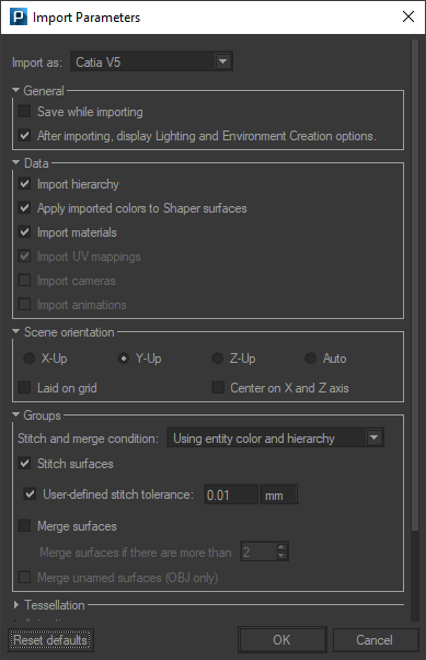
Import Parameters dialog box for a CATPart file
Depending on the FBX file you wish to import the following options will be available:
General
If the Save while importing checkbox is ticked, Patchwork 3D will first ask you:
to save your CAD model import in a P3D file format that can be interpreted by Patchwork 3D,
whether or not to save the rendering cache (for more details please refer to the following chapter: P3D Database).
Note
Save while importing allows you to save the P3D file at regular intervals to avoid saturating the memory when the CAD model being imported is large. Please note that this option has an impact on the import time.
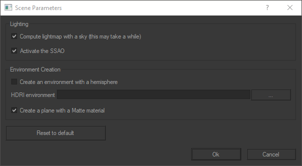
If the After importing, display Lighting and Environment Creation options checkbox has been ticked, at the end of the import the Scene parameters window is displayed, so that you can select the elements constituting the creation of a scene, that is to say its lighting and its environment. Details of the available options can be found below in the section Automatic scene preparation
Automatic scene preparation
If the box After the import, display the lighting and environment creation options has been checked, at the end of the import, the following window is displayed.

Check the desired options and Patchwork 3D takes care of the rest to create the scene with its lighting and environment.
The option Create an environment with a hemisphere is particularly useful if you want your model to be quickly staged in a very realistic environment. Patchwork 3D will take care of creating for you a hemisphere, an environment and a environment material. The latter will be automatically assigned to the surface of the hemisphere. The HDRI environment files recognized by Patchwork 3D are HDR and EXR. You can also add a plane with the shadow of the imported model to your scene (cf. Matte material ).
Tip
If you do not select an HDRI environment, Patchwork 3D will automatically apply the Studio environment on the surface of the hemisphere.
Import Options
The table below lists the available options (✔) depending on the import formats.
Options | Data | Groups | Advanced Options | ||||||||||||
Importer | Format | Save while importing | Import Colors | Import Materials | Import UV | Import Cameras | Import Hierarchy | Stitch | Merge | Merge unamed | Scene Orientation | Tessellation | Log | P3D Xml Settings | Specific Options |
|---|---|---|---|---|---|---|---|---|---|---|---|---|---|---|---|
ACIS | Acis xml | ✔ | ✔ | ✔ | ✔ | ✔ | ✔ | ✔ | ✔ | ✔ | |||||
Acis sat | ✔ | ✔ | ✔ | ✔ | ✔ | ✔ | ✔ | ✔ | ✔ | ||||||
Catia V4 | ✔ | ✔ | ✔ | ✔ | ✔ | ✔ | ✔ | ✔ | ✔ | ✔ | ✔ | ||||
Catia V5 | ✔ | ✔ | ✔ | ✔ | ✔ | ✔ | ✔ | ✔ | ✔ | ✔ | ✔ | ||||
IGES | ✔ | ✔ | ✔ | ✔ | ✔ | ✔ | ✔ | ✔ | ✔ | ✔ | ✔ | ||||
NX | ✔ | ✔ | ✔ | ✔ | ✔ | ✔ | ✔ | ✔ | ✔ | ✔ | ✔ | ||||
Pro/E | ✔ | ✔ | ✔ | ✔ | ✔ | ✔ | ✔ | ✔ | ✔ | ✔ | ✔ | ||||
SolidWorks | ✔ | ✔ | ✔ | ✔ | ✔ | ✔ | ✔ | ✔ | ✔ | ✔ | ✔ | ||||
Step | ✔ | ✔ | ✔ | ✔ | ✔ | ✔ | ✔ | ✔ | ✔ | ✔ | ✔ | ||||
Parasolid | ✔ | ✔ | ✔ | ✔ | ✔ | ✔ | ✔ | ||||||||
✔ | ✔ | ✔ | ✔ | ||||||||||||
Solid Edge asm | ✔ | ✔ | ✔ | ||||||||||||
Solid Edge prt | ✔ | ✔ | |||||||||||||
3ds | ✔ | ✔ | |||||||||||||
Obj | ✔ | ✔ | ✔ | ||||||||||||
STL | ✔ | ||||||||||||||
FBX | ✔ | ✔ | ✔ | ||||||||||||
DXF | ✔ | ||||||||||||||
LWO | ✔ | ||||||||||||||
Parasolid (*) | Wire | ✔ | ✔ | ✔ | ✔ | ||||||||||