The Configuration Browser tabs
It consists of three different tabs.
The Scene tab
Accel VR is designed to explore multiple products and multiple KDRs at the same time to create what is known as a layout or staging.
Below are the actions available to manipulate a product or set of products in the viewport.
Icon | Action | Description | |
|---|---|---|---|
 | Show | Shows the selected product. | |
 | Hide | Hides the selected product. | |
| Open | NoticeNew features in Accel VR 2021.1 Opens the product or a layout to display it directly in the viewport. | |
| Open a database or layout | Open the database repository. From the database repository, you can Import a product or a layout from your computer's hard drive or from the Lumis 3D web service. 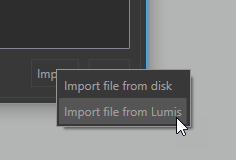 NoteDepending on the database weight, the import can take several seconds. The default address provided for the Lumis 3D server is https://lumis3d.lumiscaphe.com/. However, you can change it with your own domain name by clicking on this icon You can then add your selection of files (product and/or layout) to the scene by clicking on the Open button. TipHold down the Shift key or the Ctrl key and click to select and open multiple databases at once. If you choose to import a file from Lumis 3D you will be prompted to identify yourself to sign in to Lumis 3D by using your login details. Browse the content of Lumis 3D to select the file you want to import, double click to open it (or single click on it, and then Open). | |
| Duplicate | Duplicates the selected product (s). | |
| Delete | Deletes selected product(s) in View. TipHold down the Shift key or the Ctrl key and click to select and open multiple databases at once. | |
| Delete all | Deletes all products at once. | |
| Save layout | NoticeNew features in Accel VR 2021.1 Save your scene layout in KPL format. |


Note
Notions on the layout of a scene.
To load multiple products in the viewport, start by opening the first product from the list. This product becomes the main product, or "master" product. Choose as the "master" product the one with the environment and post-processing attributes that you want to apply to your scene. Regardless of the opening order, you can freely modify the "master" product in the list by selecting another: the gray checkmark  turns orange
  .
.
The Scene tab consists of four accordion menus.
Configuration
The Bookmarks allow you to run and combine different configuration options.
Tip
Your database must contain configuration bookmarks set up prior to export and created in the Library tab of the Create Configurations editor in Patchwork 3D
Timelines
The Timelines allow you to animate your model with different data prepared in advance in Patchwork 3D.
Notice
New features in Accel VR 2021.1
Icon | Navigation mode | Description | |
|---|---|---|---|
| Go to start | Starts the animation in reverse mode. | |
| Play | Plays the animation. | |
| Pause | Pauses the animation. | |
| Stop | Stops the animation. | |
| Loop | Repeats the animation in a loop. |


It is also possible to control the animation with the cursor.
Transformation
In this section you can position, resize, and configure the instance of your product in the 3D View with the X, Y, Z axes.
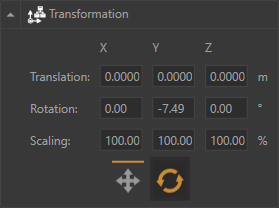
The Transformation accordion menu
Cameras
This section allows you to display camera bookmarks and, add new ones by clicking on this icon  . You can also edit
  each camera bookmark you have created in Accel VR by renaming them and changing their position.
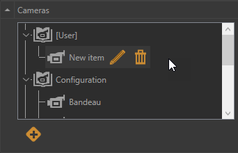
The Cameras accordion menu with a camera bookmark created by the user.
The Plugins tab
The Plugins tab lists the manipulators used by your device according to the license you purchased.
Please refer to the chapter on Advanced system settings for more details on the operation of the manipulators.
Here below the list of available plugins:
 Clipping planes management
The clipping planes plugin allows you to section the object of the scene in a pre-designated plane to see its interior. Active clipping planes are visible in all open View and will clip through all products.
With the accordion menu  you can directly:
show (Active)
 or hide
  the clipping planes.
move
 a clipping plane depending on the chosen X, Y, Z axis.
rotate
 a clipping plane depending on the chosen X, Y, Z axis.
Click on this icon  if you need to refine the settings of the clipping planes: grid steps, color, thickness, etc...
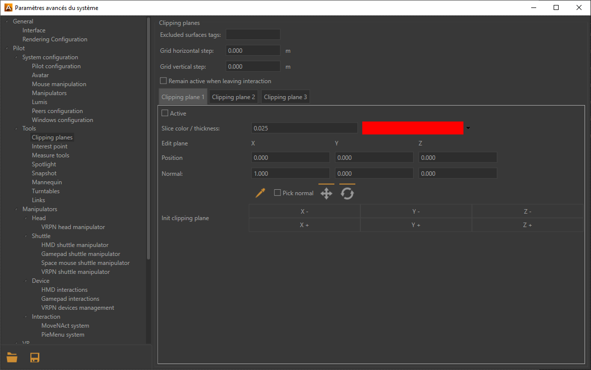
Clipping planes window
Tip
Tags used in Patchwork 3D to exclude surfaces from the clipping planes must be titled the same way in Accel VR.
For more information, please refer to the Clipping planes (Editor) chapter in the Patchwork 3D documentation. Accel VR excludes by default the label with the title NoClip.
Note
Clipping planes are positioned in the world. Consequently, moving a product in the world will not move the plane. The position at which the plane clips the product will be modified.
You can set the horizontal spacing (Grid horizontal step) and the vertical of the grid (Grid vertical step) by entering values or using the up and down arrows on the keyboard.
Accel VR Pilot allows you to manage and display three clipping planes simultaneously.
Check Remain active when leaving interaction if you plan to combine the use of clipping planes with other interactions.
Tip
Make sure the Active box is checked to display a clipping plane.
However, you can exclude certain surfaces from the clipping planes by entering in the Excluded surfaces tags field the surface tag you want to exclude. If you have several surfaces to exclude use semicolons between each tag.
You can choose the color of the slicing-edge and modify the Slice thickness of the line by entering a numerical value, or by using the up and down arrows of the keyboard.
 Selects a point of the surface in which the clipping plane passes through the surface that you want to section.
 Clipping planes example with 1 section |  Clipping planes example with 2 sections |
 Interest point management
The interest point plugin allows you to point an area that you need to focus on like a pointer during a slide presentation.
You can directly choose the color of the pointer by collapsing the accordion menu or by clicking on this icon .
Tip
Make sure the Interest point management checkbox is ticked in the Pilot configuration tab to be able to use this feature.
 Measure tool management
The Measuring Tools shows the distance between two points that you have chosen. This distance between these two points may thus be represented visually in the active view.
Tip
The option Show gizmo must be checked to use the eyedropper.
With the accordion menu you can directly:
measure a length between two points
calculate an angle
Measure a length
Click on the eyedropper
and select your starting point (Point A) in the viewport.Then click on the endpoint (Point B) to measure the length between the two points
The result is displayed directly in the viewport or in the field named Length AB.
Note
If you want to measure another length, just click the eyedropper again to restart the procedure described above.
Calculate angles
The option Compute angle allows you to display the value of an angle between two segments. To measure an angle, do the following:
Check Compute angle, the fields Length BC and Angle ABC appear.
Click on the eyedropper
and select the starting point (Point A) in the viewport.Then click on the intermediate point (Point B) to measure the length between the first two points (Length AB).
Click on the endpoint (Point C) to measure the length between the intermediate point and the endpoint. You automatically have the length of the second segment (Length BC) and the value of that angle (Angle ABC ).
Tip
Repeat the procedure from point 2 each time you want to measure an angle.
In case you realize that you need to change the position of a point, instead of redoing the whole measurement procedure you can change its position individually. To do this click on this icon and select the point you want to change with the eyedropper. You can repeat the measurement as many times as you want. The lengths and angle ABC will automatically update.
The Measure tool management window gives you the following information:
the coordinates of each point
the length of each segment
the value of the Angle ABC
 Spotlight management
The spotlight allows you to illuminate your model.
With the accordion menu you can directly:
Activate or deactivate the spotlight.
Move the spotlight in the scene with the Translation gizmo
 .
.Change the orientation of the spotlight in the scene with the Rotation gizmo
 .
.
Please find below the spotlight settings available from this icon .
You can enable or disable the Spotlight, adjust its intensity with the slider, and choose the color of the lighting. You can also adjust the intensity of the light reflection (Specular intensity). The more the cursor moves to the right, the more the setting is magnified.
 Snapshot management
The snapshot plugin allows you to snapshot a scene in VR according to the operator's point of view.
You can directly capture the viewport by clicking on the Snapshot button in the accordion menu .
Click this icon to select the folder in which the snapshots will be saved or to set the dimensions of the snapshots while the Snapshot FOV sets the point of view angle.
 Mannequin
The mannequin allows you to simulate and see the movements of your body in a 3D environment.
You can directly access its configuration by clicking on this icon or on the Advanced system settings from the accordion menu .
In the Advanced system settings, you can
display the mannequin skeleton
display or hide the mannequin's head
activate the advanced tracking mode (five trackers are required)
Vive Trackers configuration:
Tip
If you are not using the Advanced Tracking Mode of the mannequin, your trackers will be placed on your feet and your waist. If you do, you will have to place an additional tracker on each forearm of your body (as close of your wrists as possible).
Start by pairing your first Vive Tracker using SteamVR (SteamVR > “Device” > “Pair Controller”).
Use your headset, navigate to the “Manage Vive Trackers” section in settings (“Settings” > “Manage Vive Trackers”).
Use the table below to associate your tracker with the corresponding role. Be aware that these roles will not be reset after your session.
Tip
We recommend that you note the roles of each tracker to easily identify them. Steam VR associates the tracker's serial number with the role.
Follow this process for each of your Vive Trackers.
Body part | Role |
|---|---|
Feet (left / right) | Feet (left / right) |
Waist | Waist |
Wrist (left / right) | Shoulders (left / right) |
How to use the mannequin in Accel VR:
The installation of the mannequin in Accel VR is carried out in 2 steps.
Size calibration (mannequin size)
Once all of your Vive Trackers are connected, select the Mannequin tool in the interactive menu.
Stand straight and trigger the interaction. If you see a Mannequin, then you can go to the next section. If not, make sure that all your trackers are connected and that you are not using the “Advanced Tracking Mode” with only 3 Vive Trackers.
Vive tracker calibration
Stand in the Mannequin’s shape and try to make your body fit as much as possible.
Trigger the interaction again to validate.
You can now use the Mannequin tool.
 Turntables
Turntables simulate the rotation of one or more products on a turntable. For example, they make it possible to visually compare several configurations of the same product from different angles.
In the accordion menu you can directly control turntables by selecting the rotation direction (clockwise and counterclockwise) or pausing the animation. It is also possible to change the rotation speed with the dedicated slider Speed (rpm).
You can also adjust the Product Spacing from this icon .
In the Turntables window, adjust the quantities + and - of the products you want to add to the scene, then select the Product Spacing and to finish click on the Start button to begin the turntable(s).
Note
The rotation is performed only along the axis of the rotation which is specific to the product.
 Links
Links
The Links plugin allows you to link a tracker to one or more products. With this feature, you can imagine moving a product naturally according to the movements of your members for example.
You can select and configure the trackers listed in the Trackers box by expanding the accordion menu or by clicking on this icon .
Follow these steps to link a tracker to one or more products.
In the Links window, select the tracker from the list.
Then with the eyedropper
pick the reference point onto the product. This allows you to link the tracker to the product.
Note
To link a tracker to multiple products, restart at step 1 (describes above) by using the same tracker but by selecting a different product at step 2.
At any time you can break the link from the tracker to the product by clicking on this icon  . Use the translation gizmos
  and rotation
  if you need to change the reference position of your link.
Product Mesh Collider
Warning
Only available with a CAD Tools license option.
Notice
New features in Accel VR 2021.1
The Product Mesh Collider is used to display the intersections between products when they collide.
When the Include avatars in the A group box is ticked, the avatars (head, controllers, hands) are included in group A for the calculation of collisions.
When the Product Mesh Collider is activated (Activate) you can set the collision behavior. The algorithm used requires dividing the products of the scene into two groups A and B. For each product, the collisions with all the products of the other group will be calculated. Collisions between two products of the same group are not calculated.
By selecting Surfaces you will visualize the intersection of the surfaces of product A with the surfaces of product B, an intersection line of the color of your choice appears.
By selecting Volumes you will visualize the intersection of the surfaces of product A within the volumes of product B, a plane of the color of your choice appears.
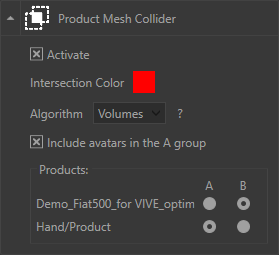
Here the Product Mesh Collider is set up with a red intersection using the intersection algorithm Volumes.
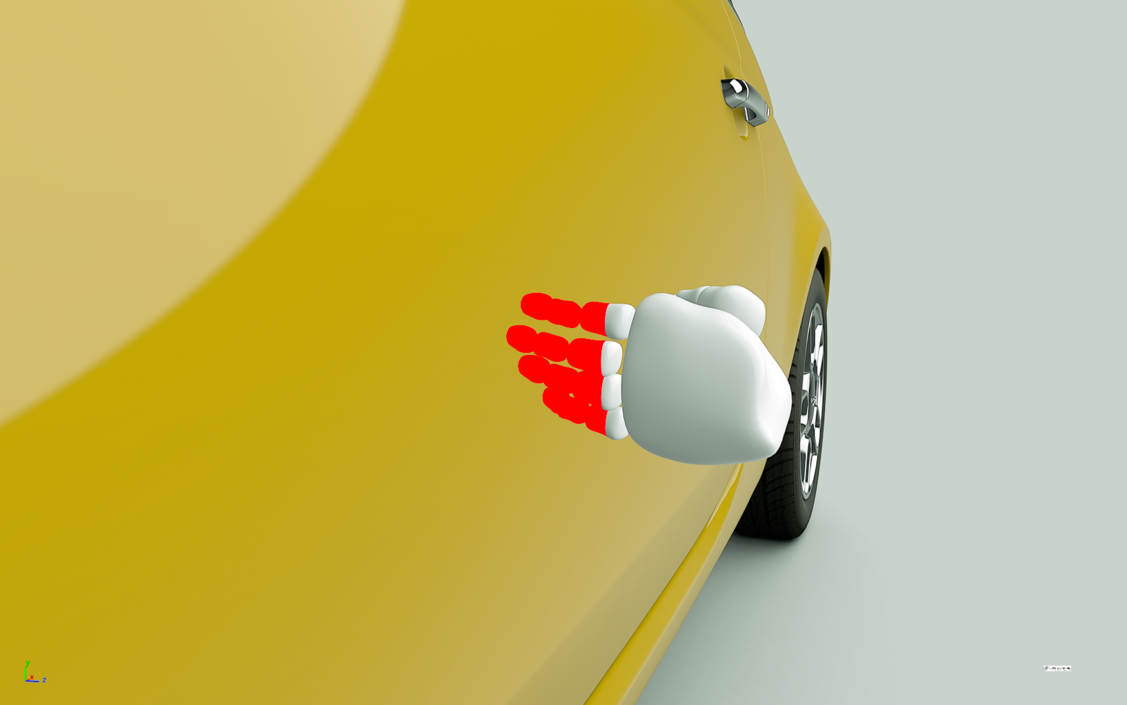
Here's the result.
The Settings tab
This tab consists of different accordion menus.
System Configuration
This section displays window status information such as coordinates (X, Y, Z), ground angle, and the number of frames per second (Render FPS).
You can reach the Advanced system settings window by clicking on this icon  .
.
For more information, please refer to the chapter on Advanced system settings for more details.
Head manipulator
To understand the operation of the head manipulator and configure it, please refer to the Head manipulator paragraph of the Advanced system settings.
Device manipulator
To understand the operation of the device manipulator and configure it, please refer to the paragraph Device manipulator of the Advanced system settings.
Interaction manipulator
To understand and configure the interaction manipulator, please refer to the paragraph Interaction manipulator of the Advanced system settings.
Shuttle manipulator
To understand the operation of the shuttle manipulator and configure it, please refer to the paragraph Shuttle manipulator of the Advanced system settings.
Windows (accordion menu)
This section allows you to configure features you desire to render in your immersive system.
Icon | Action | Description | |
|---|---|---|---|
| Hide rendering window units | Hides the window of each rendering unit (gray icon) to configure their graphics card for example. NoteThe window for each rendering unit is displayed by default. | |
| Unit windows always on top | Keeps the windows of the rendering unit in the foreground among all the windows of the Microsoft Windows® operating system. NoteDisabled by default. | |
| Eye | If the display of the eyes is reversed by a projector (frequent with certain stereoscopic configurations), click on to switch between the left and right displays. NoteDisabled by default. |


Please find below the window of the Advanced system settings available from this icon .
Depending on your needs you can select or deselect the settings below to improve the rendering performance of render units:
Mirrors
Displays the reflections of other geometries in the scene in planar mirrors. This option can greatly increase the number of elements to be rendered in a scene. To save resources this option is disabled by default. You can disable it in order to increase rendering fluidity.
Post-processes
Background
Overlay
Enhanced bump
Material, Color, Lightmaps, Wireframe change the representation of the model to be displayed.
Overwrite background
If necessary, you can also overwrite your background with a solid color or with a gradient of two colors. Check the Overwrite background checkbox to make your choice.
Accel VR can automatically display the available windows of the shuttle over the network.
Click on this icon to choose each window you want to use. The icon of the selected window turns orange to inform the user that the window has been added to the list. The question mark  then disappears. You can now close the window of the Advanced system settings.
Back in the accordion menu titled Windows, you will then see a brief description of the window (its IP and name) that you just added.
Tip
This icon means that the shuttle window has not been added to the list yet. It is unknown. This icon  means that the dedicated calculation unit to the window of the shuttle is not available over the network despite the fact that it has been added to the list.
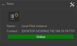
Peers
This section displays the status of the added peers.
Warning
This feature requires a specific license.
Please find below the window of the Advanced system settings available from this icon .
Accel VR can automatically display available peers over the network.
You can also manually add a peer that is on a remote network by clicking and by entering its IP address and the port.
We recommend that you choose a different color for the identification of each peer.
Click on this icon to choose each pair you want to use. The icon of the selected window turns orange to inform the user that the window has been added to the list. The question mark then disappears. You can now close the window of the Advanced system settings.
Back in the accordion menu titled Peers, you will then see a brief description of the peer (his IP and name) that you just added.
Note
This icon means that the shuttle window has not been added to the list yet. She is unknown. This icon means that the calculation unit dedicated to the shuttle window is not available on the network despite the fact that it has been added to the list.
 ZSpace management
From the accordion menu you can activate the zSpace or Invert eyes to swap the display from left eye to right in the event that your views rendered by your glasses are reversed for each eye.
This setting is very useful with some stereoscopic setups that invert the display.
To improve rendering performance in the Accel VR viewport, you can select/deselect the following renderings: Backgrounds, Mirrors, and Overlays. The configuration is accessible from this icon .
 HMD management
From the accordion menu you can optimize the rendering by checking or unchecking the parameters below:
Render in HMD
By default, the rendering display is projected in a virtual reality headset. But you can choose not to display it to relieve the system in the rendering calculation by unchecking this box.
You can also choose to disable rendering in Pilot by clicking on this icon
 located in the toolbar.
Render mirrors in HMD
Render post-processes in HMD
Render enhanced bump in HMD
From this icon you will find the above rendering parameters as well as the operating status, model, and manufacturer of the device, plus the following parameters.
Notice
New features in Accel VR 2021.1
The Rendering Mode allows you to select the appearance of your product:
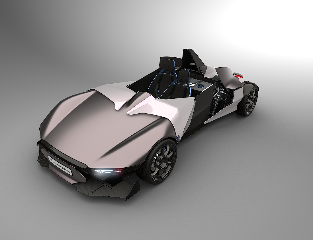
Material displays product textures,
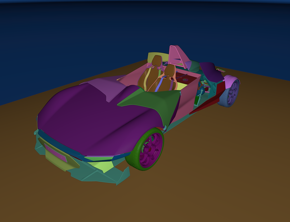
Color displays a different color for each surface used by the product,
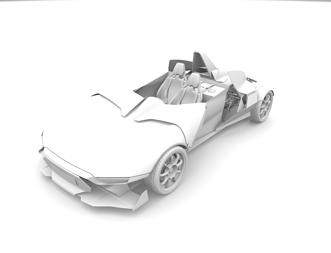
Lightmaps display the lighting rendering of the product.
The Eye separation is initialized with the default value of the headset, however, this value can be modified in the dedicated field.
The HMD render scaling slider is useful for zooming out the world so that your model fits the dimensions of the screen of the VR headset.
Canon MREAL management
Warning
The Canon MREAL headset is only available in Japan and on request.
Notice
New features in Accel VR 2021.1
From the accordion menu you can optimize the rendering by checking or unchecking the parameters below:
Render in HMD
By default, the rendering display is projected in a virtual reality headset. But you can choose not to display it to relieve the system in the rendering calculation by unchecking this box.
Display Canon MREAL background
From this icon you will find the above rendering parameters as well as the operating status, model, and manufacturer of the device, plus the following parameters.
Render mirrors in HMD
Render post-processes in HMD
Render enhanced bump in HMD
Display Canon MREAL background
When the parameter is activated, it displays the headset image which is the augmented reality instead of the product background.
Display hands
Canon MREAL technology recognizes and scans the hands of your body so that they are directly displayed in augmented reality. If the parameter Show hands is activated. Accel VR redraws the hands in the foreground with a color of your choice (parameter: Hand color). A specific tracker is required for the Canon MREAL to work correctly in augmented reality.
 VRPN devices management
The VRPN device management allows you to add, configure, and delete a VRPN device.
Accel VR supports ART, VICON, and NaturalPoint tracking systems.
Accel VR Pilot establishes the link between the render units and the trackers, gamepads, etc ... The connection is made via a local server.
Install ART or VICON equipment according to the manufacturer's recommendations. Accel VR Pilot 2020.1 must be linked with the machine on which the VRPN server of ART or VICON is installed.
The important parameters to remember from a VRPN server are: its IP address, the main tracker name (in the case of tracked glasses), and its index.
The VRPN server must receive information from the tracker(s) (please refer to the manufacturer's user documentation).
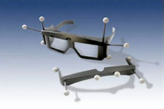
3D glasses
To use peripherals allowing navigation in the 3D scene (Logitech® controllers, Xbox 360® controller for Windows®, etc.), simply connect them to the machine on which Accel VR Pilot 2020.1 is running and install the peripherals drivers. A space mouse may also be used too.
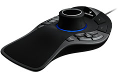
SpaceMouse® Pro
This icon has the same action as the button Open advanced config from the accordion menu . It opens the VRPN device management plugin.
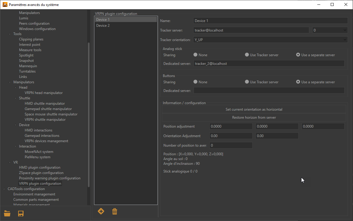
VRPN Manager
VRPN Manager consists of two parts:
The left part to add
or delete a VRPN device.The right part to configure a device.
Please refer to the manufacturer documentation of the selected device to know the IP address of the Tracker Server. The following drop-down menu 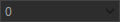 provides to Accel VR Pilot 2020.1 by VRPN protocol the current position of the tracked devices. The digit represents the sensor ID of ART tracking systems. It is normally worth 0 with Vicon systems.
Select the tracker orientation with the following arguments (Y_UP, Z_UP_X_LEFT, Z_UP_X_RIGHT, Z_UP_Y_LEFT, Z_UP_Y_RIGHT) depending on the manufacturer specifications. If the Y_UP convention is not used by default by the tracking system, data provided will be converted by the tracking framework.
If your VRPN device has an analog stick or buttons, the Analog-stick and Buttons boxes will allow you to configure them. Select the Use tracker server radio button if your device is communicating on the same tracking server configured earlier in the VRPN manager. If, on the contrary, the VRPN device does not have an analog stick and buttons such as tracked glasses, select None in both boxes.
In case your device does not communicate on the same tracking server, you then need to associate an analog stick or buttons on a separate server. To do this select the button Use a separate server. Then enter the server address in the field Dedicated server.
The box Information / configuration allows you to adjust the horizontal orientation of the device and make adjustments regarding its positioning in space thanks to the fields X, Y, Z coordinates.
 Calibration management
Expand the accordion menu and then click the Correct trapezoid button to calibrate the projection areas of the CAVE.
See details in the Operating principles chapter to understand how Accel VR works with a CAVE.
In the toolbar click on this icon  to display the rendering in your immersive system.
Then click Start warping button.
A test pattern is projected by all render units in the system.

Sample test pattern projected during the calibration procedure for the projection areas.
On each unit, proceed as below (assuming you will use a gamepad for the calibration process):
Press A button of the gamepad to configure the bottom edge. Using the joystick or the paddle (for the pixel precision) of the gamepad, reposition this edge so that its projection overlaps the bottom of the corresponding screen. Then press the B button on the gamepad to select the lower right corner and repeat the setting to place the corner so that its projection overlaps the bottom right of the corresponding screen.
Do this for all corners and edges that require adjustment in the order of the buttons shown in the table below.
A | B | B | Y | Y | X | X | A |
|---|---|---|---|---|---|---|---|
Lower edge | Lower right corner | Right edge | Upper right corner | Top edge | Upper left corner | Left edge | Lower left corner |
Positioning the upper right corner with the joystick of the gamepad.
When an image is rendered, Accel VR will distort it to compensate for the keystone projection resulting from the position of the projector. The model’s normal proportions will be restored in the projection areas.
Areas outside of the test pattern will always be displayed in black to restrict the projection to the intended screen.
Note
Accel VR saves the configuration of the Calibration Projection Areas. However, you can change the calibration at any time by repeating steps 4 and 5.
 Proximity Warning management
In an immersive system using walls, the observer is often unaware of the edges of the observation area and of the placement of the screens. To prevent the observer from running into the screens, a proximity warning is available.
With the accordion menu you can directly activate or deactivate the proximity warning option.
It is possible to modify the default settings of the proximity alert such as its Minimum distance, its Maximum distance or its Color by clicking on this icon .
The proximity warning colors the display and shows a grid with the color of your choice whenever an obstacle (the screen) is detected within a defined zone around the observer's head (Minimum distance and Maximum distance). This zone is defined in terms of the distance from the center of the observer's head.
You can also force its display (Force to maximum) in case the grid does not appear.
 CAD Tools management
Warning
Only available with a CAD Tools license option.
The CAD Tools plugin allows you to import a 3D model from third-party CAD software and interact in VR directly with it by distorting it, rotating it, moving it, or adding the curves. The changes can then be imported back into third-party CAD software.
Environment management
Choose here the folder where materials are located in order to display them in the interactive menu.
Common parts management
This tab allows you to choose the folder where common parts are located in order to display them in the interactive menu. See details in the Common parts import section.
Materials management
Choose here the folder where the materials are located in order to display them in the interactive menu.
You can also choose to change the Selection frame color in the interactive menu or to modify the Selection frame width of images.
Refer to the Material assignment paragraph for more information.
Image management
This tab allows you to choose the folder where pictures are located to display them in the interactive menu.
You can also choose to change the Border color and the Border thickness of images.
Data management
The operating mode is similar to the Timelines section. You can indeed snapshot several previews of your model by clicking on the button  to export them to your 3D software. The minus button
  deletes a snapshot.
Options tab
Choose in this tab the units you want to use to move a part. For example, the Move part interactive menu has units for translating a surface. The Options tab allows you to precisely set the translation units and rotation factors to move a part.
[1] An overlay is a 2D image (often a logo) that is displayed in front of the objects in the 3D world. It does not move when you navigate in the 3D world but remains stationary with regard to the screen.