Settings for the Selected Plane
The Enabled function in the Clipping Plane zone must be checked to view the clipping plane.
The Clipping Plane zone provides the planar equation used to define the clipping plane. You can modify it by providing new numerical values.
Alternatively, you can choose a cross-section plane in the Select the Plane zone:
Select the desired cross-section plane in the drop-down list.
Via the function Pick Plane, you can perform a cross-section starting with a plane directly selected in the active viewport, using the eyedropper tool, or alternatively a precise cross-section point by checking the Position option.
Note
The cross sections are represented automatically in the interactive view each time the eyedropper tool is used.
Creating a Contour

The contour of the clipped surface edges can be visually represented by enabling the Show option within the Contour zone. The color of the contour can be modified by clicking on the colored square to open the color selector. You can also modify the thickness of the line by entering a numerical value, or by using the up and down arrows of the keyboard.
Additional Display Options
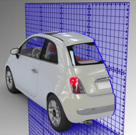
The Plane box proposes a set of display options for the active cross-section plane.
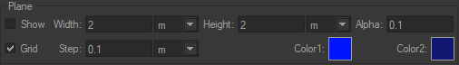
Thus the display of a plane can be activated (Plane zone > Show checkbox) and the value of its transparency (Alpha field), size (Width and Height fields), orientation, and Color of its representation (Color1 and Color2) can all be modified. Alternatively, just a metric Grid is displayed (Grid and Step options).