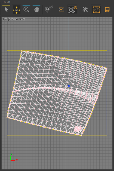
2D UV Zone
In the unfolding workshop interface, the UV-mappings obtained are displayed in the 2D UV zone. The user can now adjust the unfolding of the surface directly from the 2D view by defining additional constraints, or by modifying or releasing existing constraints. The position of the texture on the surface is updated simultaneously, which allows the user to view the effects of the adjustments.
Icon | Operation | Description |
|---|---|---|
| 2D Translation Gizmo | Adjust manually the unfolding in relation to the UV. |
| Pan | Pan in the 2D view. |
| Zoom | Zoom in the 2D view. |
| Edit control points | Adjust manually the unfolding in relation to the UV. |
| Background | Enable/disable the display of the background textures (see the Main Toolbar subsection). |
| Zoom Selection to Fit | Reframe the 2D view and center it on the selected unfolded surface. |
| Auto Zoom Selection to Fit | Enable/disable the automatic reframing of the view on the unfolded surfaces when they are selected. |
| Edit parametrization margin | Open an editor for defining margins around the unfolding so that it will be easier to use after export. |
| Show bounding-box | Enable/disable the display of the previously defined margins. |
| Export parameterization | Open an editor for configuring and then exporting the 2D image of the unfold that has taken place. In this way you can use your surface-unfolding work with graphic creation tools to edit textures that are perfectly suited to the programming of your surfaces. |


Defining a Constraint
The user can convert the markers previously set on the surface in the 3D view into constraints either by simply left-clicking in the UVW Mapping window or by using the Convert Markers to Constraints option accessed by right-clicking in the 2D view.
For a surface unfolded using the One-click option in the Hit Mode tab of the Surfaces panel, the three vertices of the triangle the marker is set on will be converted into constraints.
For a surface unfolded with the Multi-constraints option, the vertices of all triangles containing a marker will be transformed into constraints.
When a surface was unfolded with the Follow Boundary option, all vertices on the corresponding boundary are converted into constraints.
These constraints are represented by yellow and red dots in the UVW mapping. Any point thus highlighted represents a constraint.
Any point in the UVW mapping may be moved to create a deformation using the Select and Translate tool from the 2D UV toolbar. The parameterization is updated in real time. Moving a point with no constraint assigned to it defines a new constraint. The point is then highlighted.
Modifying a Constraint
To modify a constraint, the Select and translate tool must be activated. The highlighted point may be set to another position by dragging it, thus modifying the constraint.
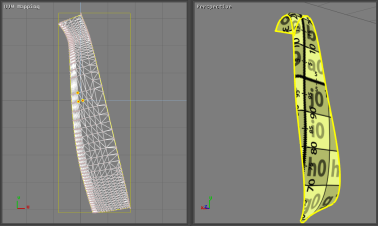
UV mapping of a surface unfolded using the one-click method and corresponding 3D view.
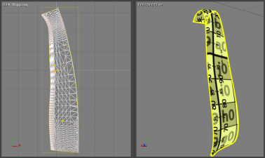
UV mapping of the surface after an additional constraint was added and corresponding 3D view.
Releasing a Constraint
To release the constraint set on a point, the option Release Constraint on Selected Point must be chosen. This option is accessible by right-clicking on the corresponding highlighted point.
All the constraints set on the UV mapping can be released at the same time by using the option Delete all markers accessible by right-clicking in the UVW mapping view.
Tip
Right-clicking inside the UVW mapping window gives access to the two options Delete All Markers and Convert Markers to Constraints. The third option, Release Constraint on Selected Point, is only displayed by right-clicking on a highlighted point.