Properties common to all types of source
To modify the properties of a light source, click on it to select it in the list of lights or in the viewport. When selected, a light source's representation in the viewport is highlighted in yellow.
The Light Source zone lists the properties of the selected light source.
Applying the Light to Surfaces
Check the box beside the light's name to enable the light source. A disabled light is visible in the 3D view in black, but casts no light.
The light source's name is displayed in the text field beside the activation checkbox. Type a new name to modify it. Validate your changes with the Enter key.
The Type drop-down list allows you to change the type of light source.
The Filter Surfaces button beside this drop-down list allows you to set up a list of surfaces to include or to exclude for the selected light source. This button opens a new window in which you can select the Type of list (surfaces to Include or to Exclude) and the mode, which allows you to apply the inclusion or exclusion to shadows only, to illumination only, or to both. Below the filter type choices are two columns listing all surfaces of the model on the left and the list of surfaces to include or exclude on the right. Select surfaces by clicking on them in the list. Then, use the buttons between the lists to move the selected surfaces from one list to the other.
Adjusting the Light Source's Properties
Color: Click on the colored square to open the color chooser and select a different color.
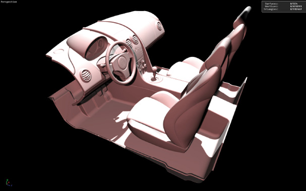
Color change visible in the instant preview of Shaper.
Intensity: Modify the intensity by entering a value in the input field and pressing Enter. Decimal values greater than or equal to 0 are accepted. The default value is 1.
IES: Light sources of type Spot, Omni, and Area can accept an IES profile. The IES profile describes the physical properties of a light source. Select an IES profile from your computer and activate the application of the profile by ticking the check-box.
Attenuation: The attenuation for light sources of type Spot, Omni, and Area can be modified. To improve performance, the contribution of a light can be canceled at a certain distance from the light source. The parameters Ramp, Full Effect and Falloff are used for setting this distance.
The list Type determines the rate at which the intensity of the light changes. Fast and slow options are available for linear and quadratic rates. You can also choose None or Physical, which provides a physically realistic rate.
The Lighting tab attenuation settings interface has been redesigned. The light attenuation type Bounded is selected by checking a checkbox. The Ramp type (linear or quadratic) is selected from the drop-down list.
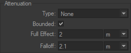
Attenuation box of the Lighting tab.
Full Effect: distance from the source for which the surfaces are illuminated without light attenuation.
Attenuation: this is the distance to light beyond which the surfaces are no longer illuminated.
Ramp: type of attenuation model applied between the Full effect and the Falloff distances.
In Preview mode, the attenuation gizmo indicates the full effect and falloff distances. It is activated by checking the Preview Bounded Attenuation check box. The surface parts illuminated without light attenuation are displayed in red. The surface parts illuminated with light attenuation are displayed in pink.
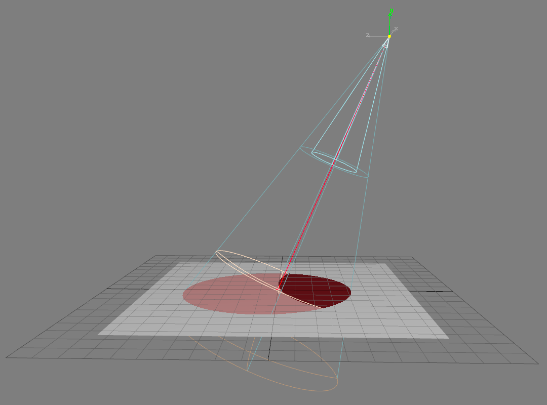
Attenuation gizmo. The sphere parts represent the full effect distance and the falloff distances.
Shadow: Shadows are cast by default by light from a light source. Unchecking the Cast checkbox disables shadows for the selected source. If shadows are enabled, the intensity and integrity of shadows can be adjusted:
Intensity: The higher the value, the lighter and more attenuated the shadows will be. The intensity must be a decimal value greater than or equal to zero. Use the Enter key to validate any changes.
Integrity: Choose an integrity from the drop-down list. Integrity values range from Weak to Max. Higher values increase shadow quality and shadow calculation time.
Positioning Light Sources
Light sources can be positioned individually or in groups.
Translating a Light Source
Select the light.
Enable the Translation gizmo
 .
.For a manual modification: hover over the gizmo to make the pointer change to four white arrows. Then, move the light source by dragging the mouse while holding down the left button.
To modify according to exact values: enter relative
 or absolute
  coordinates in the dialog box.
Modifying the Orientation of the Source
Select the light.
Enable the Rotation gizmo
 .
.For a manual modification: hover over the gizmo to make the pointer change to a white rotating arrow. Then, orient the light source by dragging the mouse while holding down the left button.
To obtain a modification according to exact values, enter relative
or absolute coordinates in the dialog box.
Making the Anchor Point of the Light Source Coincide with the Viewport
Select the light.
Orient the viewpoint of the 3D window so that the viewport would be looking directly into the light in its desired position.
Click on the Align the light on the camera
 icon. The light is aligned to point to the camera.
Positioning a Selection of Multiple Light Sources
Two modes exist for applying transformations to a selection of lights:
Icon | Function | Description |
|---|---|---|
| Transform selected surfaces using the pivot of the leader selection | The transformation is applied to all selected lights relative to the pivot of the selection leader (whose gizmo is displayed in white). |
| Transform selected surfaces using their own pivot | The transformation is applied to all lights in the selection relative to their own pivot. |


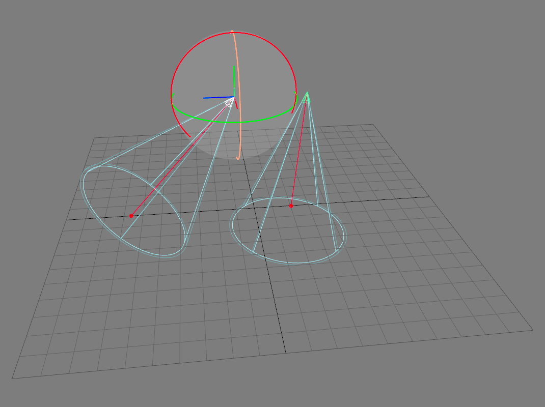
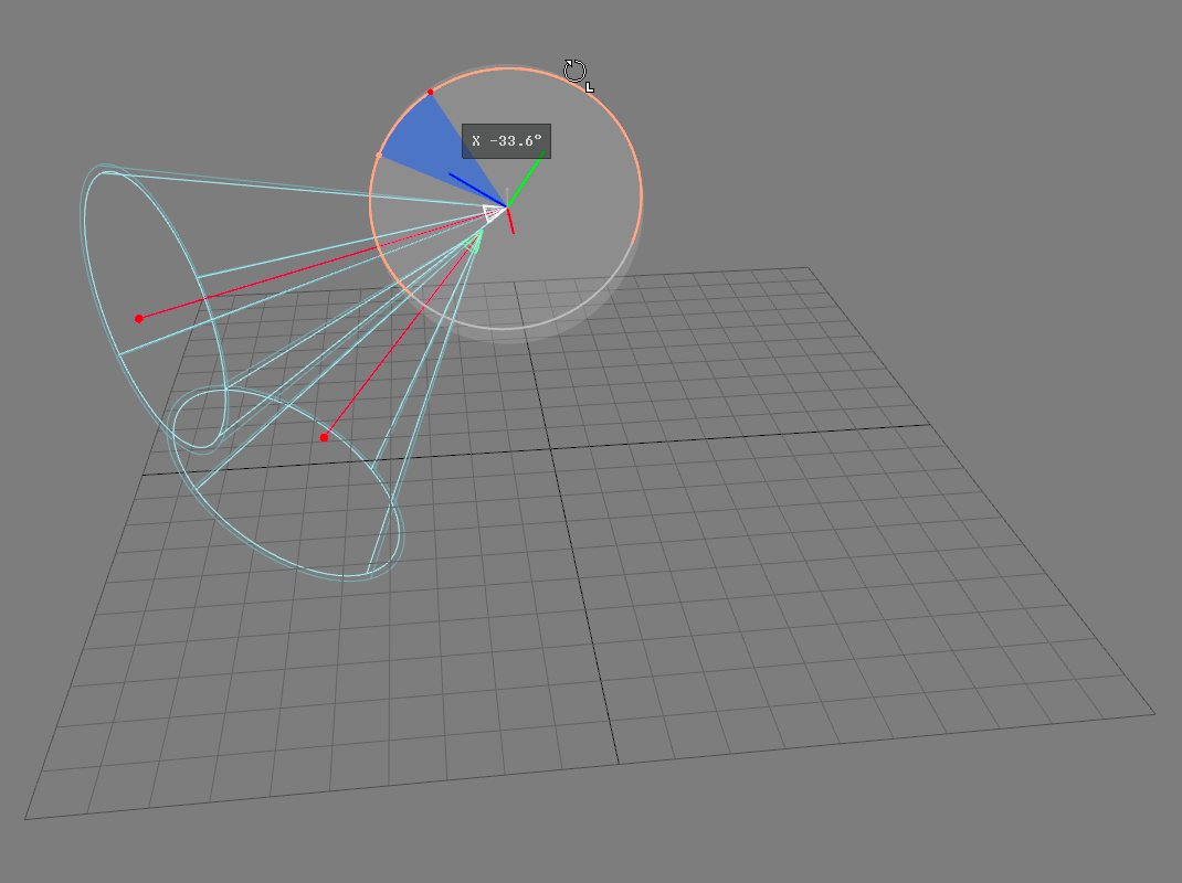
A selection of two lights. The light selection leader’s gizmo is displayed in white.
 | 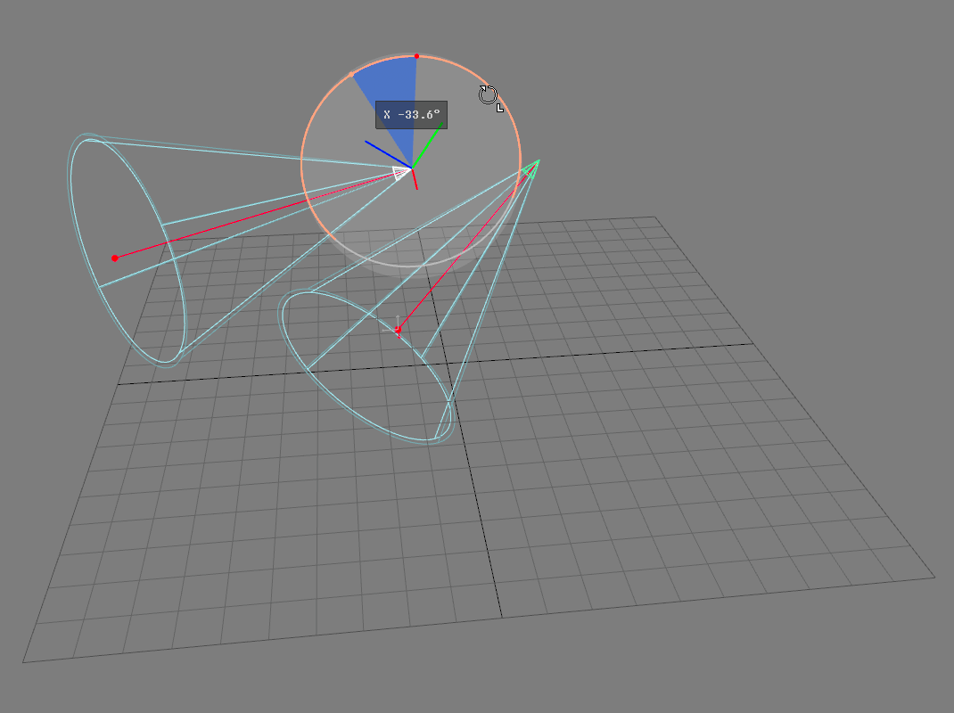 |
A rotation is applied to a light selection relative to the selection leader’s pivot (left) or relative to the lights’ individual pivots (right).