Example: Creating Configuration Rules
Note
This example of configuration rule creation for the color of a truck cabin is based on database toy_truck_tuto.p3d. You can obtain this database by emailing our support team @ support@lumiscaphe.com.
First, aspect layers need to be created for the configurable elements.
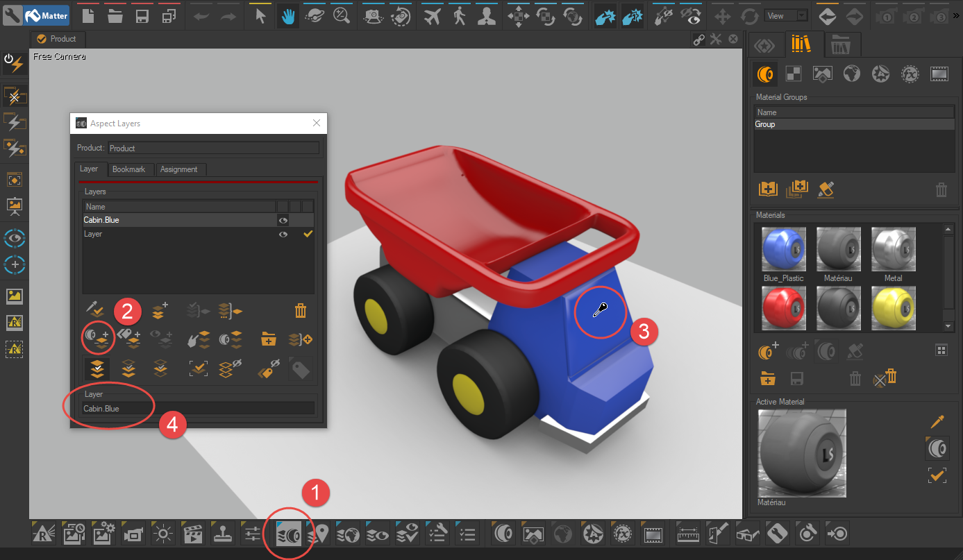
In Matter, open the Aspect Layers window by clicking on this icon
 at bottom of the interface.
Select the Split by picked material tool.
Click on an element linked to the configuration to create an aspect layer.
Rename the aspect layer created by following the naming principle: "partition.value" (for example: Cabin.Blue).
The use of this naming system lets you automatically create configuration rules (see next paragraph). Using it therefore saves considerable time.
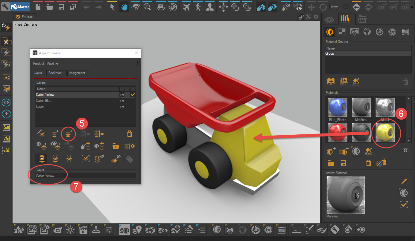
Click on the Duplicate the Aspect Layer button to create a variant of the element linked to the configuration.
Drag-and-drop a new material on the element in order to assign to the aspect layer the new value taken by the element linked to the configuration.
Rename the aspect layer according to the newly assigned value (in our example: Cabin.Yellow).
Create as many variants as necessary by repeating steps 5 to 7.
Create new configurable elements by repeating steps 2 to 4, and then create their derivatives by repeating steps 5 to 7.
Note
Patchwork 3D also lets you create product derivatives relating to geometry.
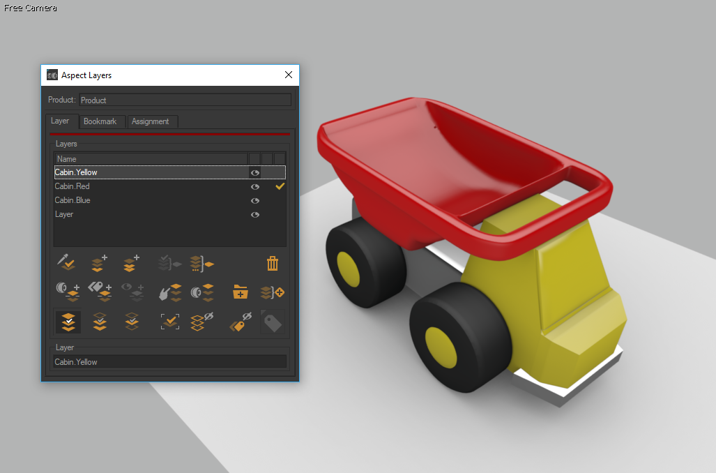
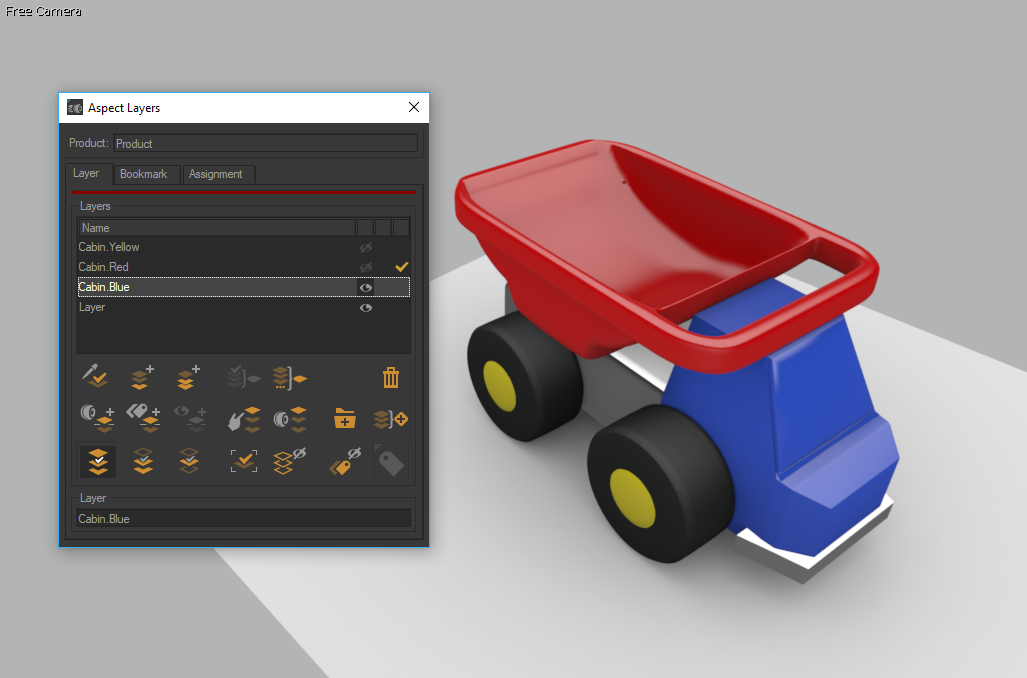
Aspect layers Cabin.Yellow, Cabin.Red and Cabin.Blue.
Click on this icon  to show dialog Configurations. In the Browser tab, select Yellow in the drop-down list. Name all layers using the same prefix "Cabin.", then drag and drop the layer selection into the Rules tab of the Configurations editor. The interface builds the following rules:
Cabin.Yellow (defined "Cabin.Yellow")
Cabin.Red (defined "Cabin.Red")
Cabin.Blue (defined "Cabin.Blue")
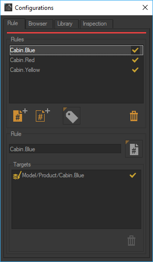
Rule Cabin.Blue determines the visibility of aspect layer Model/Product/Cabin.Blue.
This set of rules follows the principle of exclusion: only one of them is evaluated as true at a time. We check that each of these new rules targets an aspect layer.
This rule set follows the exclusion principle: only one of them is evaluated as true at a time. Each of these new rules targets one aspect layer. Symbols Cabin.Yellow, Cabin.Red and Cabin.Blue are added automatically as a drop-down list to the available symbols in the Configurations Browser. Selecting Yellow means defining the symbol Cabin.Yellow. Since only one of these symbols can be defined at a time, only one of the new rules is evaluated as true. A partition corresponding to the color of the cabin was created.
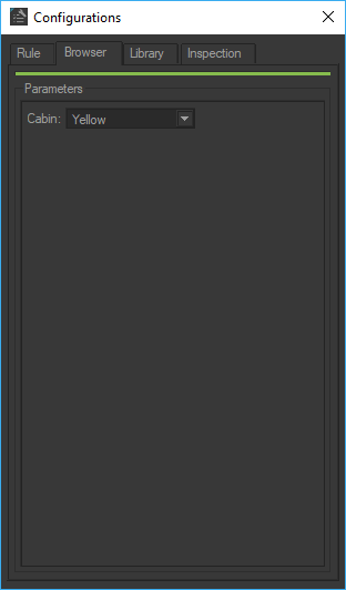
Drop-down list generated automatically from the symbols involved in the new rules.
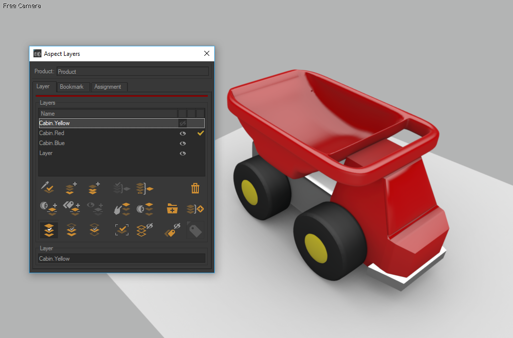
In the Browser tab, select Yellow from the drop-down menu. In the Inspection tab, the Cabin.Yellow rule appears in green because it is true. The aspect layer Model/Product/Cabin.Yellow is then visible. The Cabin.Red and Cabin.Blue rules appear in red because they are false. The target layers of these rules are hidden.
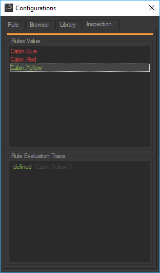
Inspection tab shows the result of rules evaluation.
Create a configuration rule for enabling or disabling the displaying of material on the ground in the same manner. First, create the aspect layer Model/Product/Ground corresponding to material assignment on the ground. Generate the rule Ground by dragging and dropping the layer from the Aspect Layers editor to the Configurations editor: the Simple Rule editor pops up, allowing for specifying the rule name and the symbol involved.
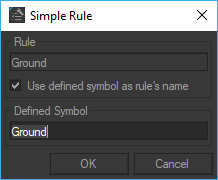
Rule Ground creation using the Simple Rules editor.
The rule "Ground" follows the activation/deactivation principle and is written:
Ground (defined "Ground")
A partition corresponding to the ground was created and a check-box for defining the symbol Ground added automatically to the list of available symbols in the Browser tab in dialog Configurations. Ticking the check-box defines the symbol.
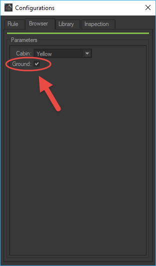
Check-box for defining symbol Ground.