Positioning Surfaces from the Main Interface
Patchwork 3D includes an area in its interface specifically for editing the positions of surfaces. This editing area is beneath the 3D viewports in the workspace. It allows for directly entering numerical values for the position of surfaces relative to axes X, Y and Z.

Editing area dedicated to surface positioning.
The toggle button Enable user input for absolute coordinates  in the toolbar is for displaying or hiding this editing area. Entering numerical values for these parameters is only possible when a surface is selected.
The toggle button Keep Ratio  of the Scale box affects the scaling behavior of selected surfaces. You can indeed choose to keep the same dimensions on all axes (X, Y, and Z) and to have a uniform scaling or on the contrary choose not to have a uniform scaling on the three axes (X, Y, and Z)
  . Here you will find explanations on how the scaling works.
Coordinates in World Reference Frame
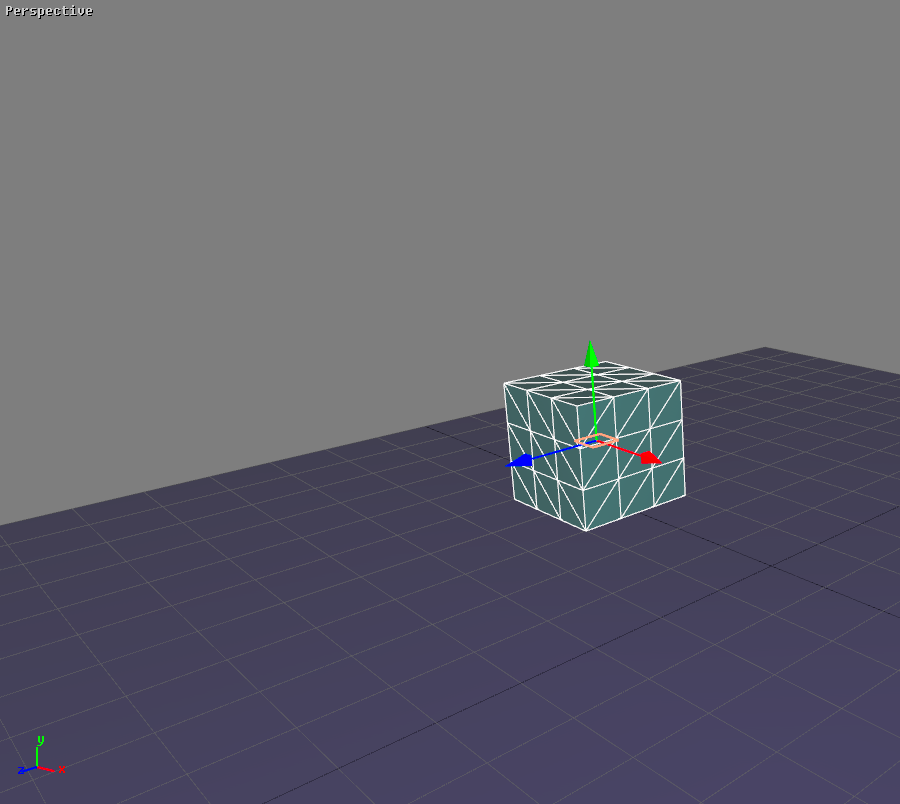
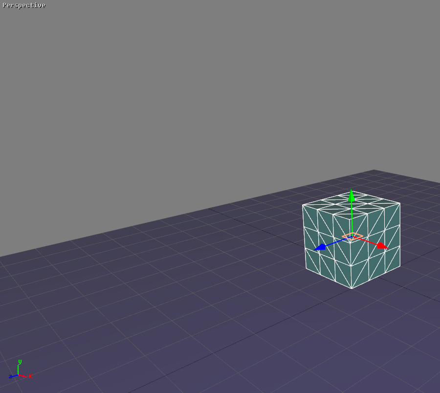
The Translation and Rotation boxes are for specifying the surface’s translation coordinates (TX, TY, and TZ) and the rotation orientation (RX, RY, and RZ) of the selected surface’s pivot relative to the World frame. The selected surface remains fixed relative to its own pivot.
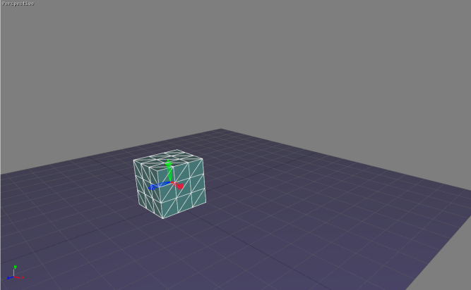 Initial position of the cube’s pivot. | 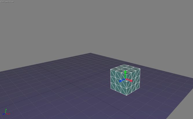 Intermediate position of the cube’s pivot after entering coordinates TX=0.5 m and TZ=-0.3 m. | 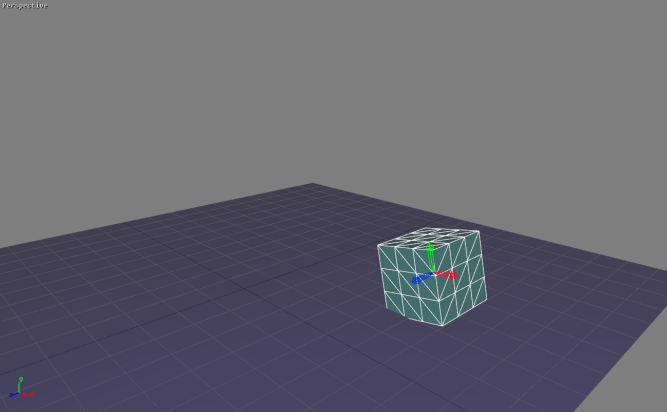 Final position of the cube’s pivot after entering angular coordinate RZ=10°. |
Note
In the Pivot mode, translation and rotation tools affect pivots only instead of affecting surface-pivot couples, which they do in the other modes.
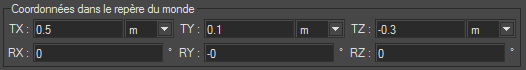
Coordinates in the World Reference Frame for the final position of the pivot shown in the previous figure.
Coordinates Relative to Parent's Pivot
The Translation and Rotation boxes are for specifying the position coordinates (TX, TY, and TZ) of the pivot’s origin and the angular coordinates (RX, RY, and RZ) of the pivot for the surface selected relative to the pivot of its parent in the kinematics chain.
|
|
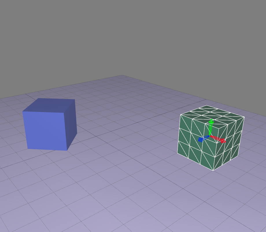
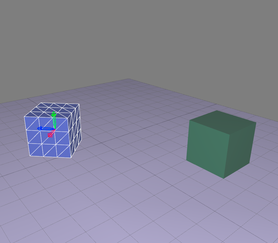

Positioning the blue cube's pivot relative to the parent surface's pivot, the green cube’s.
When no parent is defined for the surface selected, the values entered are considered to apply to coordinates in the world frame reference like in the first box.
Relative Translation and Rotation
The function Enable user input for relative rotation or translation  may be accessed only when either the Translation or Rotation gizmo is activated. It displays the Relative translation or rotation dialog box.
The value by which the surface selected is translated relative to the frame of the gizmo displayed is entered in fields TX, TY, and TZ. The value by which the surface selected rotates relative to the axes of the frame of the gizmo. The frame of the gizmo depends on the frame of reference selected.
The cube's translation gizmo origin is located at XX X=-0.4 m (on the left). A translation of 0.3 m in the direction of the World frame’s X axis is applied to the cube (final position on the right).
Applying a Transformation to a Selection of Surfaces
Two modes exist to apply a transformation to a selection of surfaces:
Transform selected surfaces regarding the pivot of the leader of the selection  : the transformation is applied to all selected surfaces relative to the selection leader (displayed in white).
Transform selected surfaces regarding their own pivot  : the transformation is performed for each surface relative to its own pivot.
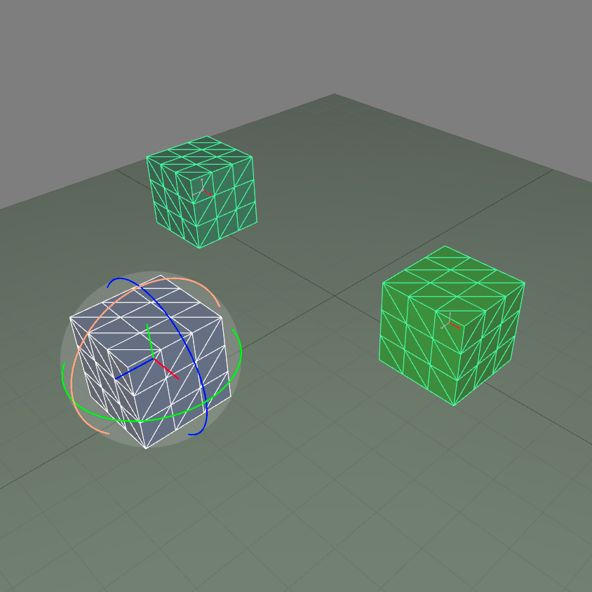
A selection of surfaces. The selection leader is displayed in white.
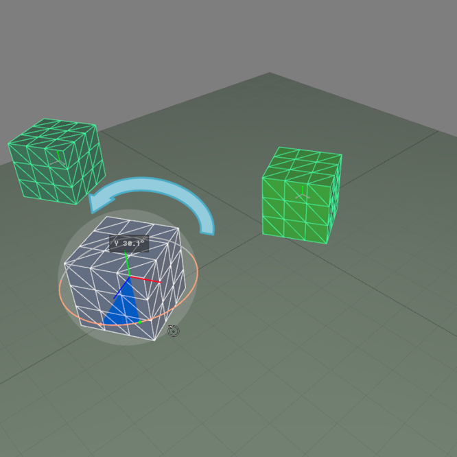
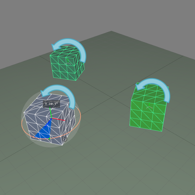
Rotation applied to the surface selection presented in the previous figure relative to the selection leader's pivot (left) and relative to the surfaces' individual pivot (right).
Defining the Step Values
The box on the right side of the area dedicated to positioning surfaces allows users to define fixed increments of movement or rotation for using the gizmos while holding down the Alt key.

Steps box for specifying the step values (outlined in yellow).