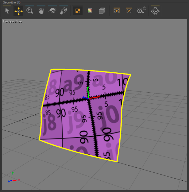
3D Geometry Zone
The 3D Geometry zone contains an interactive 3D view in which the surfaces to be unfolded and several tools for unfolding and manipulating the surfaces are displayed.

The 3D Geometry toolbar changes its look depending on the following operation modes: Unfolding or Stitch.
Icon | Operation | Unfolding | Sew | Description |
|---|---|---|---|---|
| Selection | ✔ | Select surfaces. | |
| Move Marker | ✔ | Select and move a marker on the unfolded surface. | |
| Zoom | ✔ | ✔ | Zoom in the 3D view. |
| Pan | ✔ | ✔ | Move around in the 3D view. |
| Orbit | ✔ | ✔ | Control the rotation of the 3D view in order to observe the surfaces from different points of view. |
| Set Render to Texture | ✔ | View the background textures of an unfolded surface. | |
| Set Render to Deformation | ✔ | View a highlighted distribution of the physical forces associated with the deformation of the unfolded surfaces. | |
| Show Wireframe | ✔ | ✔ | Enable/disable the display of the surfaces' wireframe. |
| Zoom to Fit | ✔ | ✔ | Reframe and center the 3D view on of the surfaces in the unfolding workshop. |
| Zoom Selection to Fit | ✔ | ✔ | Reframe and center the 3D view on a selection. |
| Auto Zoom to Selection to Fit | ✔ | ✔ | Enable/disable the automatic reframing of the view on the unfolded surfaces when they are selected. |
| 3D Selection Only | ✔ | ✔ | Limits the display of the 3D view to the surface being unfolded. To return to a view of all selected surfaces, click on this button again. |
| Show/Hide seam curve point for selected seam | ✔ | Show the seam curve points. NoteBy default, the seam curve points are displayed. | |
| Show/Hide seam mesh | ✔ | Show the mesh of the seam. NoteBy default, the geometry band mesh is displayed. |
In the Unfolding tab, a right click on 3D Geometry Zone you can:
Delete a marker,
Insert New Marker After,
Delete All Markers,
Convert Markers to Constraints.


