Understanding Partitions
 |  |  |
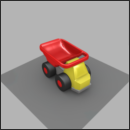
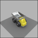
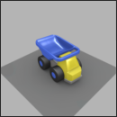
A partition with three possible states.
To create a configurable model, begin by identifying the partitions within which several alternatives are possible. In the above image, the truck’s bin can exist in multiple colors. The bin color is an example of a partition. Partitions can be related to model surface geometry, aspect or position, or to the environment of the model. In this example, for ease of understanding, aspects and colors are used to illustrate the principles of configurations.
There are two types of partitions. Some can be enabled or disabled, while others require an element to be chosen from a list of multiple alternatives. Partitions are listed in the Configuration Browser, where you or your end user can select their state:
Next, the partitions must be associated with rules.
In the above image, the partition "stickers" can be enabled or disabled. By ticking the checkbox "stickers" (on the left in the image), you define the corresponding symbol. The associated rule, "stickers" (on the right), states that when the symbol "stickers" is defined, the aspect layer containing the stickers is visible.
In this image, the partition "paint" refers to the color of the paint, which can be any one of several options: red, blue, yellow, black… By making a selection in the drop-down list (on the left of the image), you define one of the symbols "paint.red", "paint.blue", "paint.yellow", "paint.black" in accordance with your choice. The associated rules (on the right), "paint.red", "paint.blue", "paint.yellow", "paint.black," state that if the corresponding symbol is defined, the layer with the right color is visible.
This example, therefore, contains a total of five symbols and five rules (one for the stickers and four for the paint), but only two partitions ("stickers", and "paint").