Configuring the Rendering in a 3D Viewport
The 3D rendering of the active view can be configured to modify the representation of the model that is being edited.
It can be accessed directly in the viewport or via the Viewport memu.
Directly from the viewport
You can change the representation of the model from the following icon  which is located at the top left of all viewports.
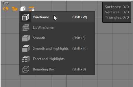
Seven rendering modes are available:
Icon | Render Mode | Description |
|---|---|---|
| Wireframe | The surfaces are represented schematically with plotting following the lattice structure of each surface. The surfaces are not mutually masked. |
| Smooth | The surfaces are shown smoothed out with solid faces, lit by soft lighting. |
| Smooth and Highlights | The surfaces are shown smoothed out, as solid faces with a specular reflection. This is the default render mode. |
| Facets | The surfaces are represented by their lattice structure, not smoothed out, as solid faces lit by soft lighting. |
| Facets and Highlights | The surfaces are represented as a solid lattice structure, not smoothed out, as solid faces with a specular reflection. |
| Lit Wireframe | The surfaces are represented by an illuminated wireframe plot of their lattice structure. |
| Bounding Box | Each surface is represented by the wireframe plot of its bounding box. This rendering mode facilitates the handling of surfaces that have lattice structures comprising a large number of triangles. |
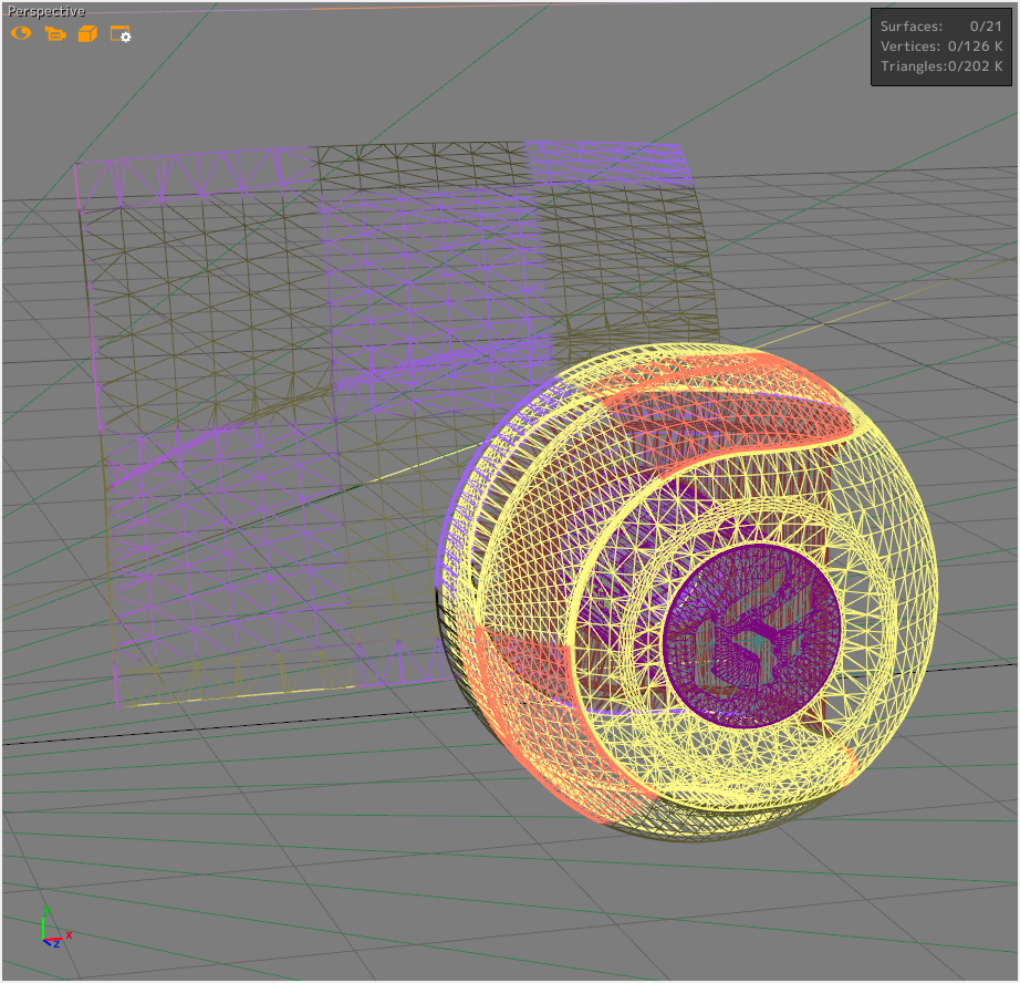 Wireframe view | 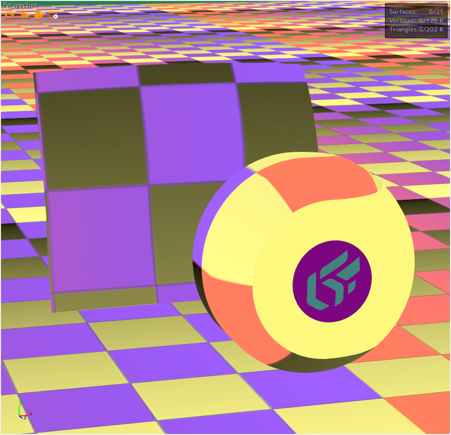 Smooth view |
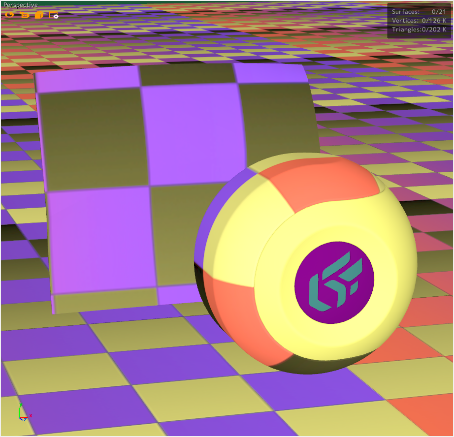 Facets and Highlights view | 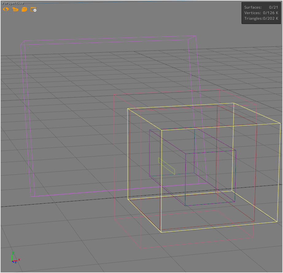 Bounding Box view |
Several options for displaying your model are available from the following icon  which is located at the top left of all viewports.
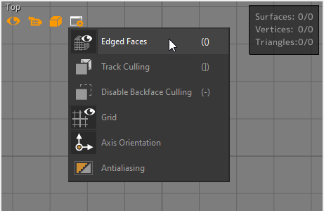
Option | Description |
|---|---|
Edged Faces | The lattice structure of the surfaces is represented as a wireframe 3D rendering overlaid on the surfaces. |
Track Culling | The hidden faces (oriented away from the observer) are shown in bright red. This mode facilitates the identification of the surfaces that are not properly oriented. |
Ignore Backface Culling | Enabled by default, this option enables the optimization of the rendering, which removes the faces oriented away from the observer. |
Grid | Displays a reference grid that facilitates understanding of the 3D viewport. The grid is enabled by default. |
Axis orientation | Displays the indicator of the different axes for the model in the bottom left corner of the window. This option is enabled by default. |
Antialiasing | The anti-aliasing improves the visual quality of the 3D rendering by deleting the aliasing effects caused by screen pixels. You have the possibility of modifying the anti-aliasing configuration in the Patchwork 3D rendering settings. 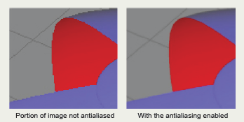 Demonstration of the smoothing produced by the antialiasing algorithm. |
From the menus
The menu Viewport > All Viewport Render > Render mode gives access to the modes (Wireframe, Smooth, etc...) described in the previous section.
The accessible options from the Viewport menu are the same as those described in the previous section.
Other viewing aids are available from the Visualization menu as Head Up Display which displays the number of surfaces, triangles, and vertices selected in the viewport.


