Editing Camera Properties
The right-hand side of the editor displays the settings of the camera being edited. Select a camera from the list on the left by clicking on it and enabling the  Edit current camera mode to view or edit the camera settings in the right-hand side of the editor. You can also double-click on the camera.
Warning
In this mode, navigation in the viewport will also modify the camera's settings.
If no camera is selected for editing, the settings for the active viewport's free camera are displayed.
You can click in the field you would like to modify and provide a new value.
Renaming the Camera
The name of the camera being edited is shown. You can modify it by clicking within this zone. It is also possible to use the button below the camera list to rename the camera.
Choosing a Sensor
To modify the associated sensor, drag a sensor from the Matter sidebar's sensor library and drop it on the Sensor field.
To remove a sensor from the camera, click on the  Remove current sensor button. This will not delete the sensor. When you remove a sensor, the camera will automatically return the default sensor settings instead.
Lens
The basic camera parameters can be set in the Photo tab or the CG (Computer Graphics) tab. The Photo tab displays the parameters in analog form, using the vocabulary associated with a physical camera as a metaphor. The CG tab allows you to provide the same information.
Photo | CG |
|---|---|
Focal length: provide the focal length. The sensor size is displayed below this field for reference. Sensor size influences the interpretation of this value. | Field of view (FOV): provide the angle corresponding to the field of view. |
Portrait mode: tick this box to impose a portrait orientation. Lenses have a landscape orientation by default. | Field of view axis: from the drop-down menu, choose the axis to which the angle of the field of view should be applied. |
Lens Shift
Patchwork 3D has a lens shift allowing you to frame your compositions regardless of their height or width.
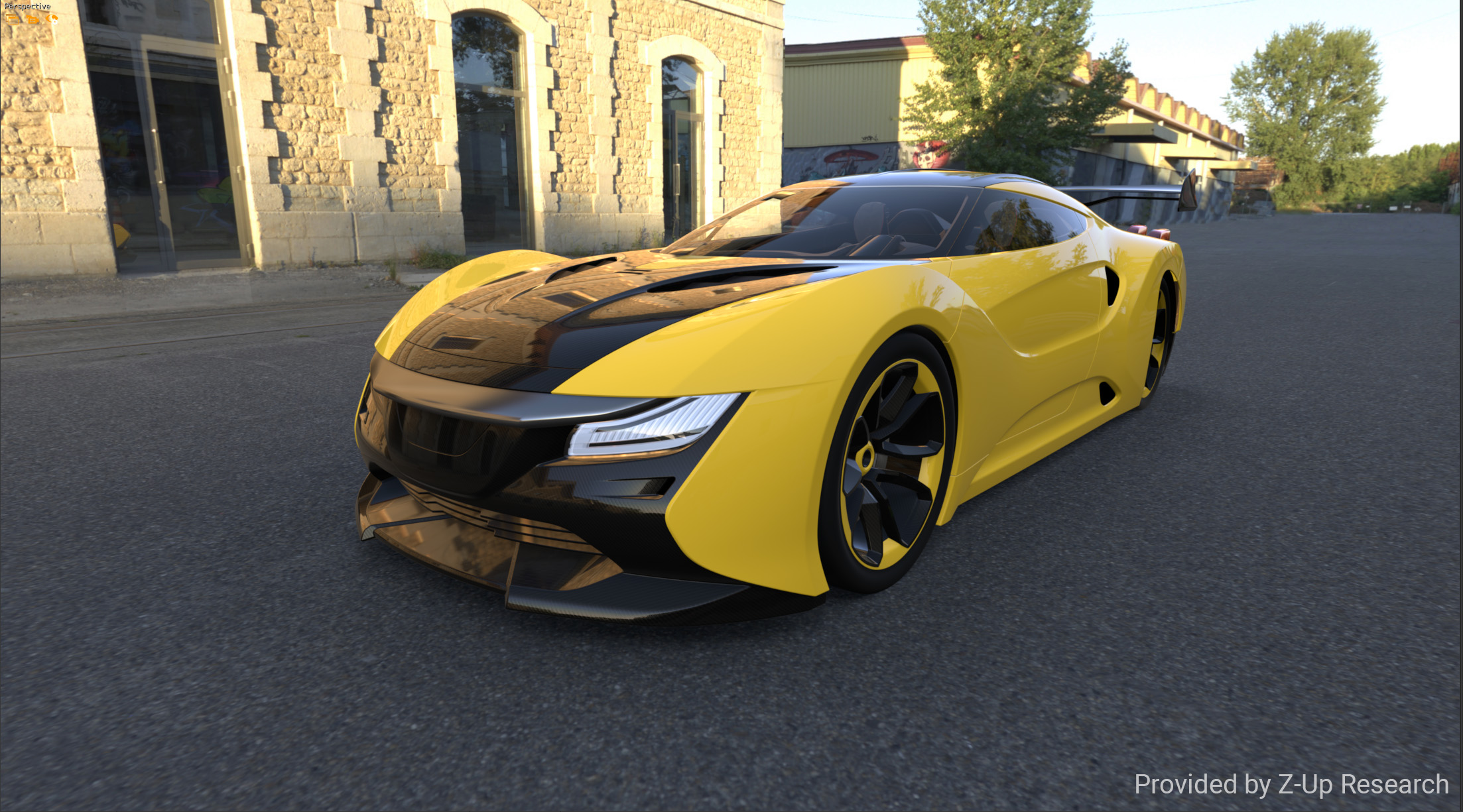
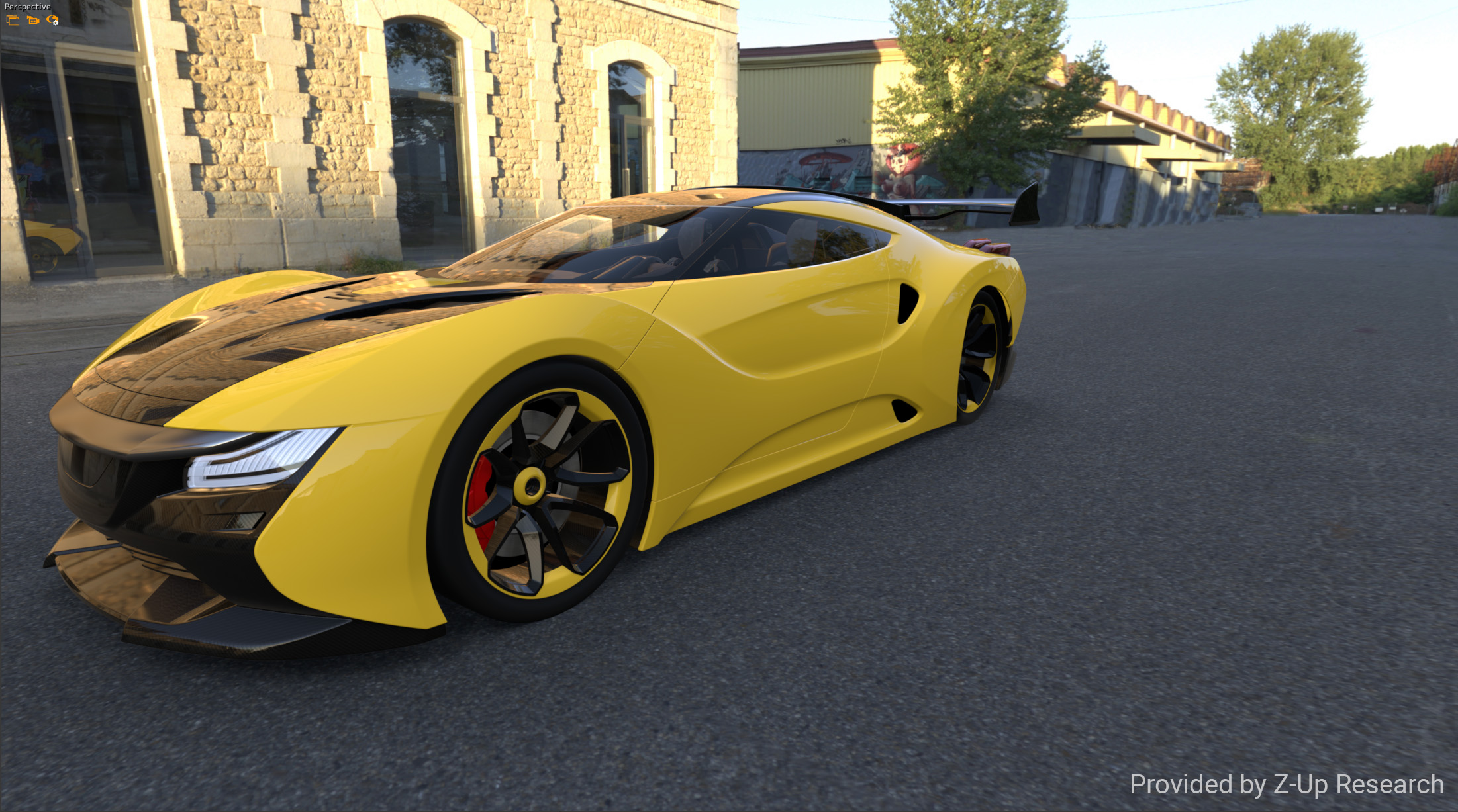
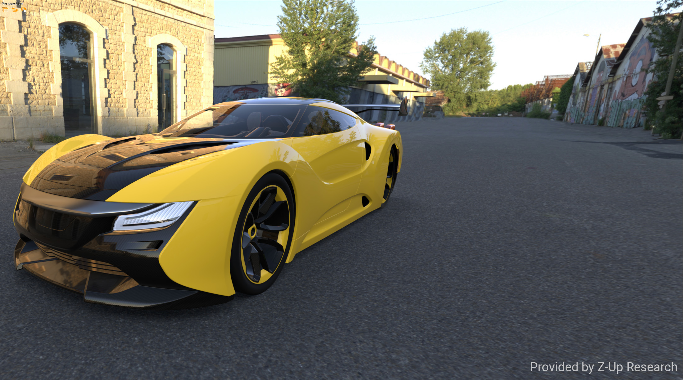
The lens shift makes it possible to capture, without perspective distortion and with the same focal length, a composition that would not normally fit into the field of the Patchwork 3D camera. By analogy with cameras, this is very often the case when you want to photograph a very tall or very wide building that does not fit entirely within the frame of the lens. To overcome this inconvenience you must either move away from the subject to enlarge the angle or tilt your camera upwards to photograph the entire building for example. This results in perspectives that may be unwanted.
Select a camera from the list on the left by clicking on it and enabling the
 Edit current camera mode to view or edit camera settings. You can also double-click on the camera.
In the upper right corner of the Cameras editor, use Shift X to correct the framing on the horizontal plane, and Shift Y to correct on the vertical plane.
Tip
You can also adjust the lens shift directly from the viewport using the  Lens Shift interaction mode available in the toolbar of Matter. More information is in the section Interacting with the 3D Viewports.
 Initial positioning of the car (centered). |  The car is moved to the left via the Pan |  The car is moved to the left via the |
Depth of Field
Note
The Depth of Field zone brings together settings that were previously available in the Depth of Field Editor for versions up to and including v5.7.
Depth of field is an effect by which objects at the focal distance from the camera appear clearly. Objects at other distances appear progressively blurrier as their distance from the zone in focus increases. This effect can be activated by checking the option Active.
By default, the depth of field is also active during navigation within a scene or when playing an animation.
Tip
For the depth of field to be displayed in the 3D viewport, antialiasing must be activated under the Render Quality Settings menu accessible from the viewport context menu. See Render Quality Settings (Editor).
For an image snapshot, the option Antialiasing must be activated in the Snapshot Images editor.
The value provided in the Aperture field sets the diameter of the aperture of the lens shutter. The aperture is expressed in millimeters.
The focal distance can be provided here in numerical form. If you prefer to define the focal distance interactively, activate the camera.
Once the camera is active in a 3D viewport, you can define the focal distance by placing the cursor over the zone where the focal point should be positioned and using one of the following keyboard shortcuts:
Shortcut | Action |
|---|---|
Ctrl+Spacebar | Places the point indicated by the cursor at the center of the focal plane. This manipulation may change the direction in which the camera is facing. |
Shift+Spacebar | Places the point indicated by the cursor at the center of the focal plane. This manipulation may change the direction in which the camera is facing. |
The smoothness of the blurriness, or quality, can be modified by moving the slider. A higher value increases the quality but requires a longer calculation time.
Motion Blur
The motion blur effect simulates the streaking effect of moving objects or a moving camera when the object or camera is moving during the time of exposure.
When the Motion Blur option is enabled, modifying the camera orientation and position produces a motion blur effect. This simulates the effect of a physical camera with the capture speed (framerate) provided in the Frames per second field.
To limit the effects on rendering speed, this effect is applied only to the camera motion by default. To apply it to animated objects as well, check the Apply to moving objects option. When applied to moving objects, place the cursor at the appropriate time in the Timelines editor to see the effects on a static image.
The motion blur effect is visible in video captures, but is not available in renders by raytracing.
Depth Range
The Depth Range box shows the automatically-calculated placement of the two Z planes between which the camera's view is in focus. You can force a different position for the Z-near and the Z-far planes by providing new values.
Point of View
A camera position: the position and the orientation of the camera.
Mode | Description |
|---|---|
From-To-Up | Provide the point (X, Y, Z) for the position of the camera, a point along the camera’s viewing vector, and a point along the vector indicating the upward vertical axis of the camera. |
Position-Orientation | Provide the point (X, Y, Z) for the position of the camera and its orientation in Euler angles. |
