Mapping Operators
Shaper offers eight different functions for defining the mapping of a surface:
Extraction for the unfolding workshop,
Planar projection,
Box projection,
Open box projection,
Spherical projection,
Cylindrical projection,
Closed Cylindrical projection,
Torus operator.
The choice of mapping operator is made through a selector in the Mapping panel of the Shaper interface. By default, no mapping operator is assigned to a surface.
Extraction
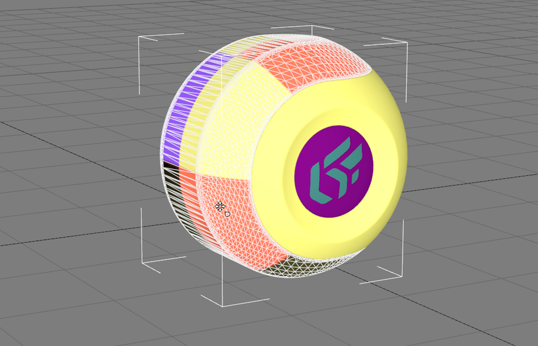
Certain 3D modeling tools can attach UV mapping information to the surfaces. When importing models, Patchwork 3D attempts to conserve this information, which remains attached to the surfaces. This is the case, for example, for importing Autodesk 3DS Max models.
Extract mapping operator allows you to apply the unfolding made in the unfolding workshop depending on the selected UV set. Cf. Unfolding & Stitch Workshop
Planar Projection
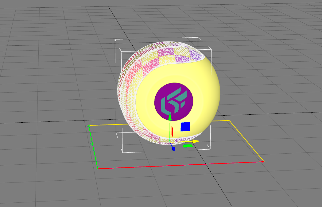
The planar projection projects a grid perpendicular to a plane. The effect obtained is similar to the projection of a transparency slide onto the surface. This type of projection is suitable for flat, sparingly deformed surfaces. The gizmo represents the plane containing the grid.
Box Projection
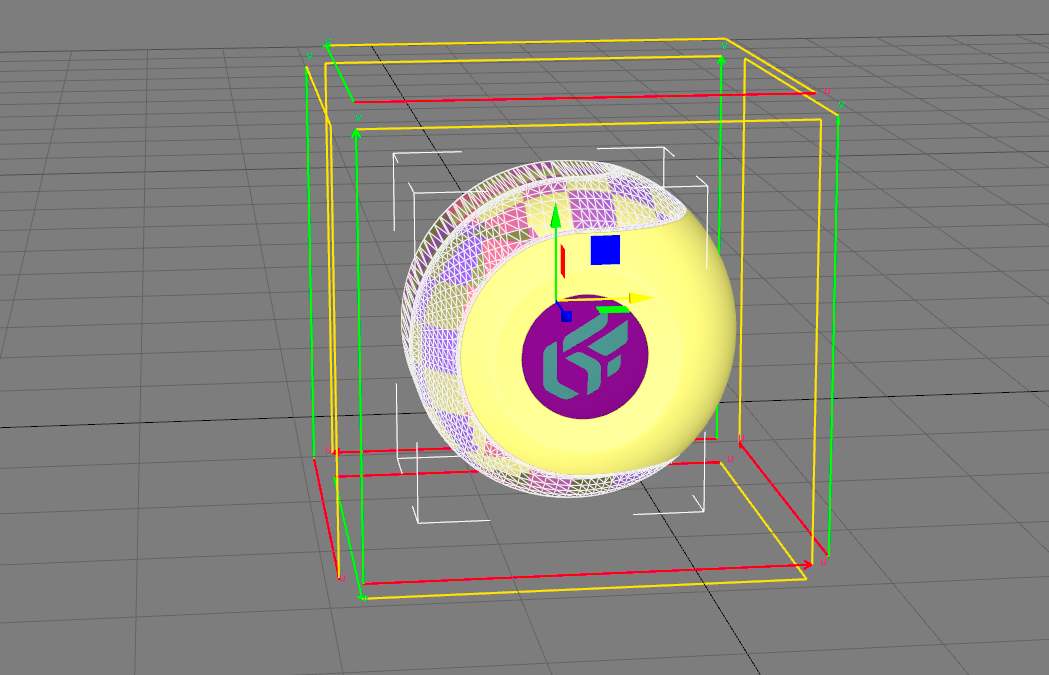
The box projection is the simplest projection to use and the one that is the most multi-purpose. The gizmo takes the form of a box that surrounds the surface. Each face of the box corresponds to a planar projection.
You can use this projection operator in most situations, since the resulting mapping grid is sparingly deformed, irrespective of the geometry of the surface.
On the other hand, the material can be cut into several pieces to cover the surface.
This mapping operator is ideal when you use uniform materials bearing no pattern.
Open Box Projection
This projection operator is similar to the Box Projection. The gizmo takes the form of a four-sided box with no base and no lid.
Spherical Projection
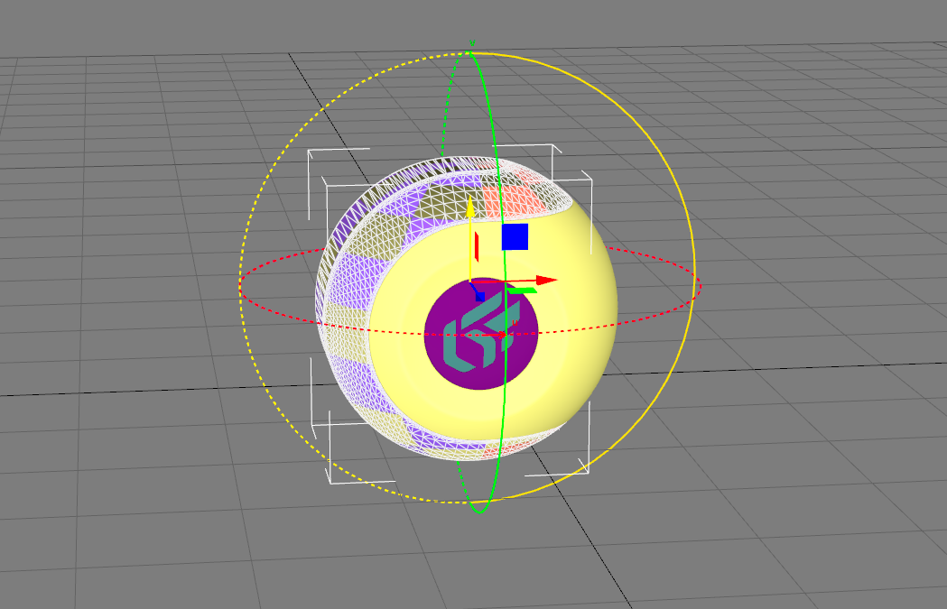
The spherical projection projects the grid as polar coordinates. The gizmo takes the form of a sphere. The longitude and latitude correspond, respectively, to the U and V axes of the grid.
Cylindrical Projection
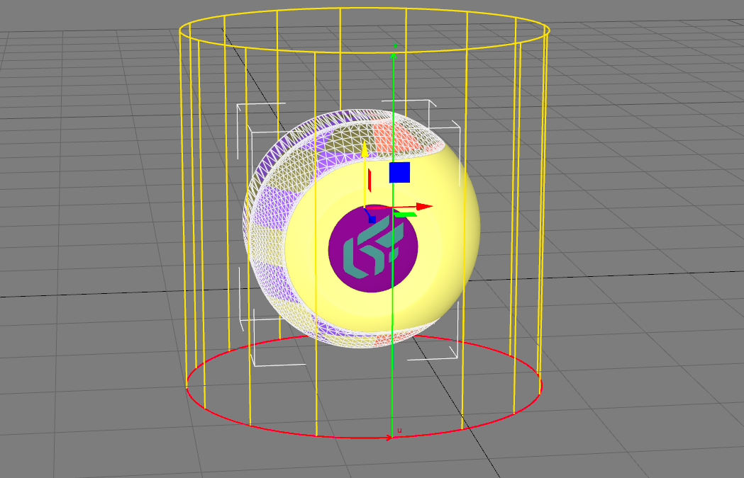
The cylindrical projection projects the grid as cylindrical coordinates. The gizmo takes the form of a cylinder. The longitude and the height in the cylinder correspond, respectively, to the U and V axes of the grid.
Cylindrical with Cap Projection
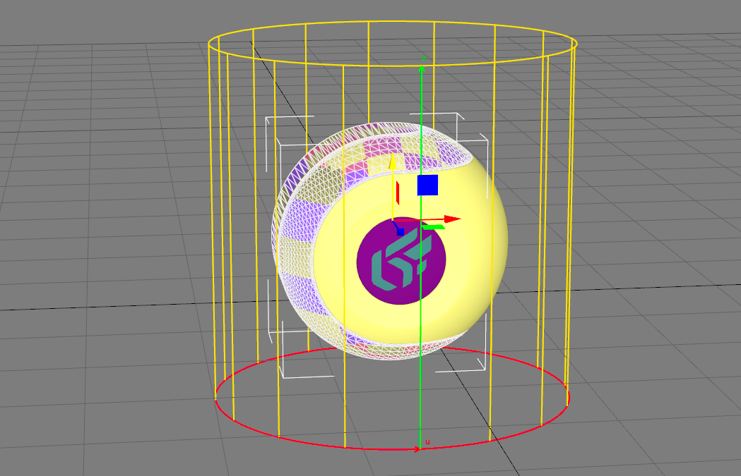
The cylindrical with cap projection is similar to the cylindrical projection. The gizmo takes the form of a cylinder that is capped at both ends.
The two faces at the ends of the cylinder behave like planar projections. The orientation of the surface is used to determine which grid should be used.