Edition zone
 Unfolding tab
The Surfaces box contains an area for exploring the surfaces involved, and three menu tabs for configuring the methods for unfolds and viewing them.
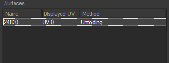
The area for exploring the surfaces lets you select the surfaces by their name and view the unfolding method used. (The selected surface is highlighted).
Each surface can combine up to 32 separate unfolding sets. At the bottom of the box, Displayed UV channel allows you to choose the set of UV targeted by the unfolding.
This zone is followed by several tabs which give access to the workshop settings.
Click Mode
The Click Mode tab provides access to the fast unfold general options.
Preprocess provides access to three types of preparation: None, Sew and Weld & Sew.
Preparation | Description |
|---|---|
None | Uses the current topology of the surface. |
Sew | Carries out a sewing operation on the edges. |
Weld & Sew | Carries out a sewing and joining operation on the edges. |
Find the description of the Surface Cutting Workshop  in a dedicated chapter. See the Surface Cutting Workshop for more information on how it works.
Welding Tolerance assigns a numerical value to the tolerance of the CV's when the Weld & Sew mode of preprocess is selected.
Method provides access to three types of unfolding methods: None, Copy and Unfolding.
Method | Description |
|---|---|
None | Remove and cancel the previous unfolding work. |
Copy | Is used to retrieve an existing unfolding method. In Copy mode, the unfolding workshop offers the choice of currently-defined UV sets. A drop-down menu allows you to browse the UV sets and select the most suitable set for unfolding the selected surfaces. |
Unfolding | Create an unfolding of the surface using the 3D view. Unfolding Properties: Technique provides access to three different unfolding techniques: One click, Multi constraints and Follow boundary. These techniques are described below. |
Tip
The Quick Assignment mode must be enabled in order to execute an unfold operation and view its representation (see "3D Geometry Zone" above).
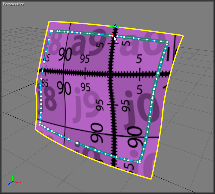
One click: is for creating a new unfold with just one click on the surface to be unfolded. The origin of the unfold is on the surface at the precise location where the click has been made. With this technique, the orientation of the texture is always positioned so that the y axis of the texture is parallel to the vertical edges of the 3D view.
 |  |
Multi constraints: is for assigning several markers to the unfold so that it precisely follows the form of the surface.
 One click method. | 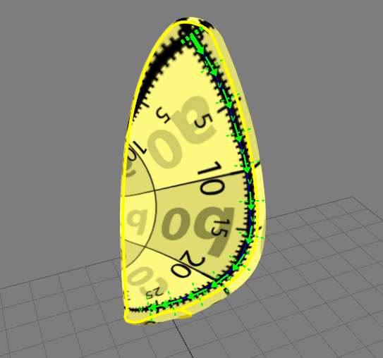 Multi-constraints method. |
Tip
It is possible to change the position of the markers at any time using the Move marker tool (see "3D Geometry Zone" above).
Follow boundary: is for constraining the unfold to a specific edge of a surface. Two markers are necessary for this unfolding technique.
 One click method. | 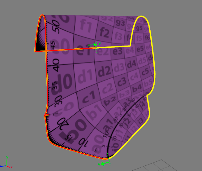 Follow boundary method. |
The Auto centered option is for positioning the origin of the texture in the center of the surface, regardless of where the click has been performed.
 Auto-centered disabled. | 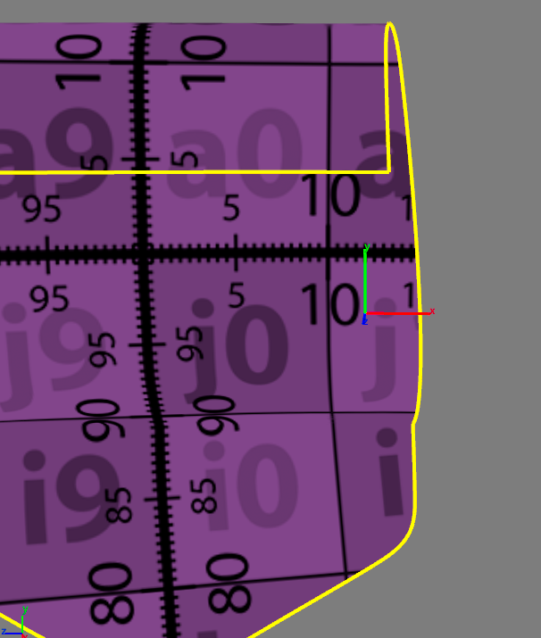 Auto-center enabled. |
Surface Properties
The Surface Properties tab provides access to the unfold options depending on the selected unfolded surface.
 : The Reset button is for re-establishing the initial unfold assigned to the surface.
The Parametrization frame provides the same unfolding options as in the Hit mode tab (see the Hit Mode Tab section).
When the unfolding methods Multi constraints or Follow boundary are chosen, the placement of markers that define the constraints are handled using the following buttons:
Icon | Function | Description |
|---|---|---|
| Place marker | Place a new marker at the clicked location on the selected surface |
| Delete all markers | Delete the markers created with the Multi constraints unfolding technique. |
| Swap boundary markers | Reverse the direction of the markers created with the Follow boundary unfolding technique. |
| Set | Confirm the adjustments made on the selected surface. |


The UV Transformation frame is for positioning the texture using numerical values.
The Automatic centering option is for positioning the origin of the texture in the center of the surface.
User Texture
The User Texture tab provides access to the properties of a user texture.
 : The Open texture button is for loading a texture from your documents.
 : The Reload texture button is for updating the loaded image.
The Dimensions frame is for assigning metric values to the texture dimensions.
 : The Reset texture dimensions button is for canceling the values assigned to the texture dimensions and for returning to the initial values.
The Preview frame is for viewing the image loaded for the texture.
 Stitch tab
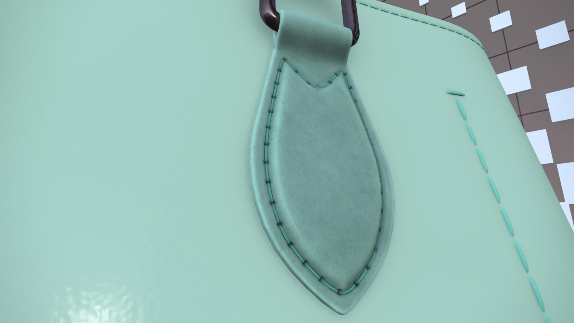
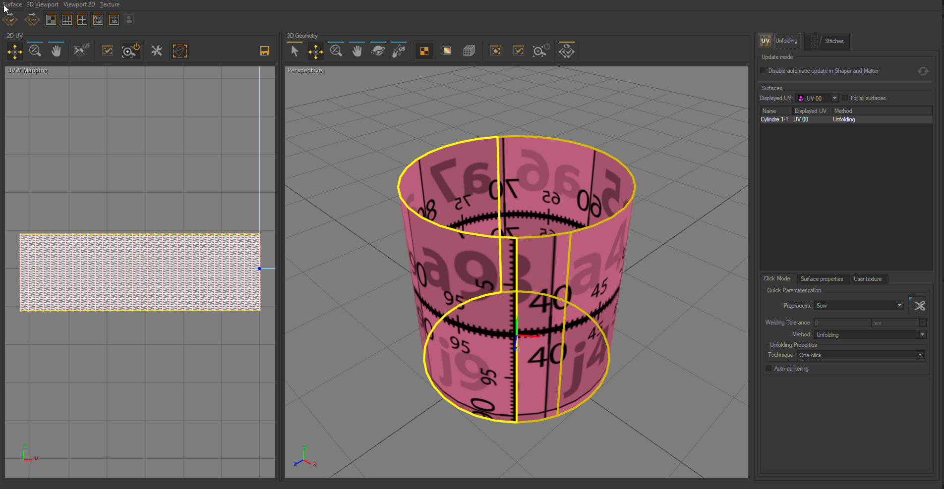
The stitch workshop creates geometry bands that support sewing materials to create realistic seams.
Note
Surfaces must be unfolded first if you want to use the stitch workshop. The following icon  helps you to identify unfolded surfaces. The UV column lists the channel on which one or more seams were made. The Seams column gives the number of seams the surface has.
Like the Unfolding tab, you can select the UV channel (Displayed UV) in which you want to stitch a seam. The parameter For all surfaces allows changing the displayed UV channel for all surfaces.
Two stitching method are available:
 Free Draw Seam freely stitches the seam on the surface without constraints.
 Follow Surface Boundary constraints the stitch to the surface boundaries.
You can adjust the Width of the geometry band which will serve as a support for the seam and set the Offset from surface to move the seam just over the surface.
You can also set the Offset from boundary. This parameter is only available with the Follow Surface Boundary stitching method.
Notice
New Features in Patchwork 3D 2021.1 X5
The Precision in length parameter increases the number of points between the markers in the geometry strip. Conversely, the lower the number of stitches, the more the seam will be straight. A straight seam, for example, requires very few stitches (simple mesh), while a sinuous seam that hugs curved surfaces generally requires a high number of stitches (complex mesh).
The Precision in width parameter increases the number of points between the markers in the geometry strip. The higher the number of points, the more detailed the geometry strip will be. Conversely, the lower the number of stitches, the more the seam will be straight. This parameter is very useful for making concave or convex a strip of geometry that simulates a seam at the border of a material (leather, fabric, etc ...).
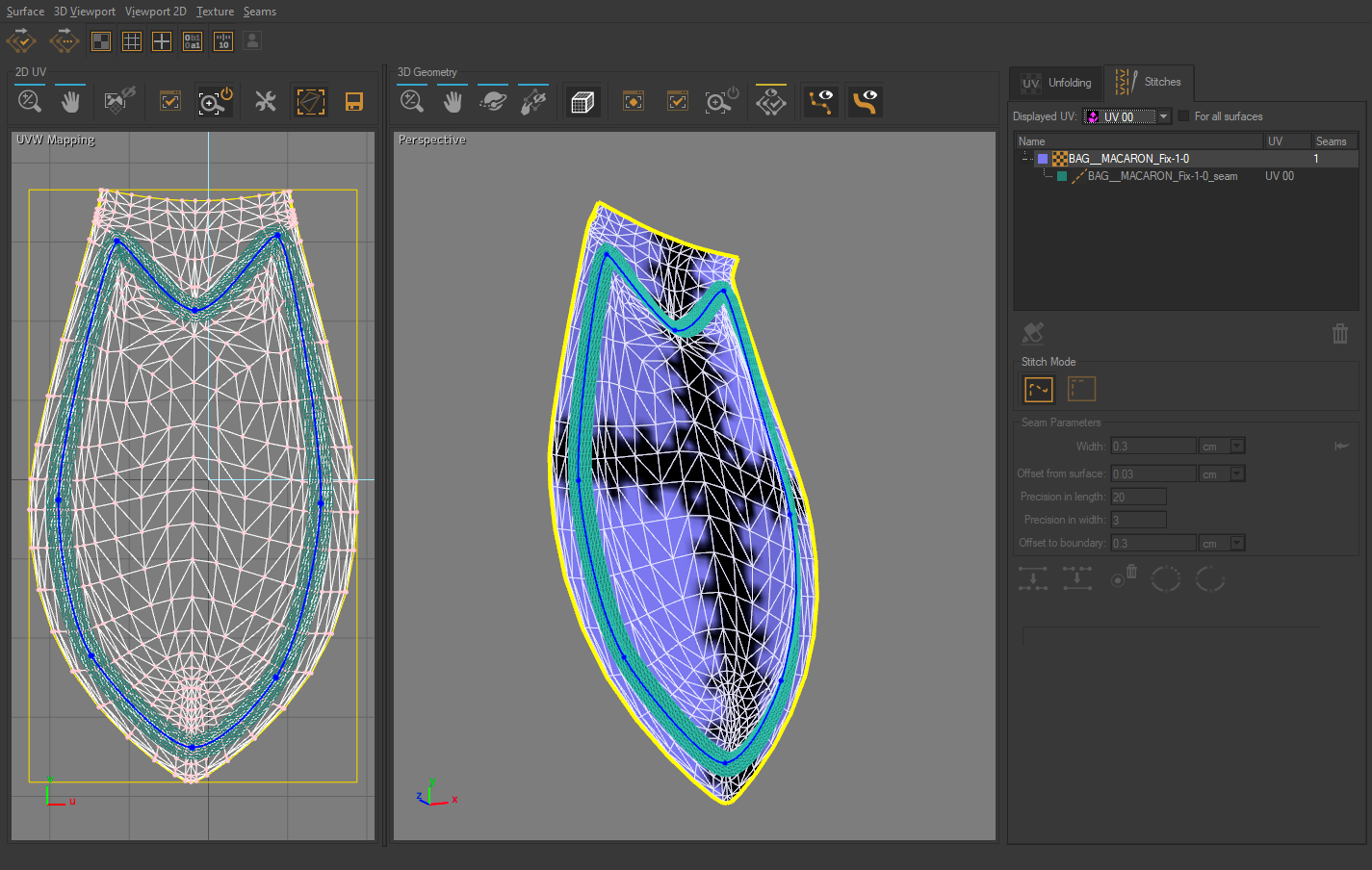
Example a geometry strip with a width of 0.3 cm with the value of 20 for the precision in length and a value of 3 for the precision in width.
Tip
It is possible to use the 2D UV and 3D Geometry zones whatever the stitching method used to create the seams. The drawn of the seam points is done in the UV Mapping (2D view). The drawn is automatically transferred to the 3D view. If some artifacts appear in the 3D view, check the place points and move them in the 2D view accordingly.
Free Draw Seam
Add as many points as necessary to create your seam. It can be open or closed. If you need to make a closed seam, right-click on the last stitch of the seam and select Close Selected Seam.
By a right-click you can change the shape of your seam using the following options:
Icon | Function |
|---|---|
Finish editing selected seam | |
| Delete selected seam point |
| Delete selected seam |
| Open selected seam |
| Close selected seam |
| Join selected seams for two open seams. |
| Split selected seams into two separate seams. To do so, select two points of the seam to identify the segment to be split. |


Tip
For more realism, you can also add curves to the seam with the following keyboard shortcuts:
Alt + click adds a tangent to the selected point.
Ctrl + click on a tangent endpoint breaks the angle of the tangent.
Ctrl + Shift + click you can change the length of one side of the tangent while keeping the same axis for both sides. The tangents of the geometry band are handled in the same way as the Bézier curves.
Free draw seam with a width of 0.6 cm and a precision of 10.
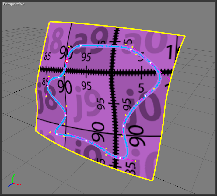
Follow the surface boundary
Two markers are needed to create a seam: one at the start of the border and the other at the end. The seam can be opened or closed.
For a closed seam to be made correctly, the start marker and the end marker must be as close as possible or even joined (see. Close selected seam).
When flying over the surface, the nearest point on the border is displayed with the green arrow. It indicates the direction that the seam will follow. The blue arrow indicates the offset of the geometry strip from the border.
Note
You can manually move a curve control point at any time. You must return to free mode to do so.
Warning
Warning: manually modified points will be ignored when modifying the Offset from boundary.
Seam following the surface boundary with a band width of 0.6 cm and an offset from the boundary of 2 cm.
Surface Cutting Workshop
Available in: Shaper: Surface > Unfolding > Edit unfolding/stitch for selected surfaces > |
The Surface Cutting Workshop is a tool available from the Unfolding/Stitch Workshop.
The Unfolding Workshop enables users to define the UV mapping of complex surfaces. However, for some surfaces, the UV mapping obtained is not always relevant. This is especially true for surfaces that can’t be unfolded onto a plane without being cut in places. In such cases, the surface cutting workshop can be used to manually work out a cutting line that will ensure a quality UV mapping. Cutting paths are defined using control points that are positioned manually.
Surface Cutting Workshop Interface
The surface cutting workshop has a dedicated interface that can be accessed from the standard unfolding workshop once a surface has been selected.
Open the surface cutting workshop by clicking on the icon in the panel on the right. The surface cutting workshop consists of four zones:
Validation commands toolbar.
3D view.
3D geometry toolbar.
Cut Properties Panel.
Surface Cutting Workshop interface.
Validation Commands Toolbar


The validation commands toolbar in the top left corner of the surface cutting workshop interface.
The validation toolbar has three options:
The green checkmark validates the defined cutting path and returns to the unfolding workshop.
The red cross discards the cutting path and returns to the unfolding workshop.
The red cross discards the cutting path and returns to the unfolding workshop.
3D Geometry Toolbar


3D geometry toolbar above the 3D view in the surface cutting workshop interface.
The 3D geometry toolbar gives access to tools for managing control points and observing surfaces. The four operating modes for navigating in the 3D view are Zoom, Pan, Orbit, and Zoom by extent.
The two tools for managing control points are:
Select and Move tool
for selecting an existing control point and moving it to another position.Quick Assignment
mode for inserting a new control point.
3D View
This window is an interactive view in which the surfaces to unfold are displayed. It possesses the same functions as all other 3D views in Patchwork 3D.
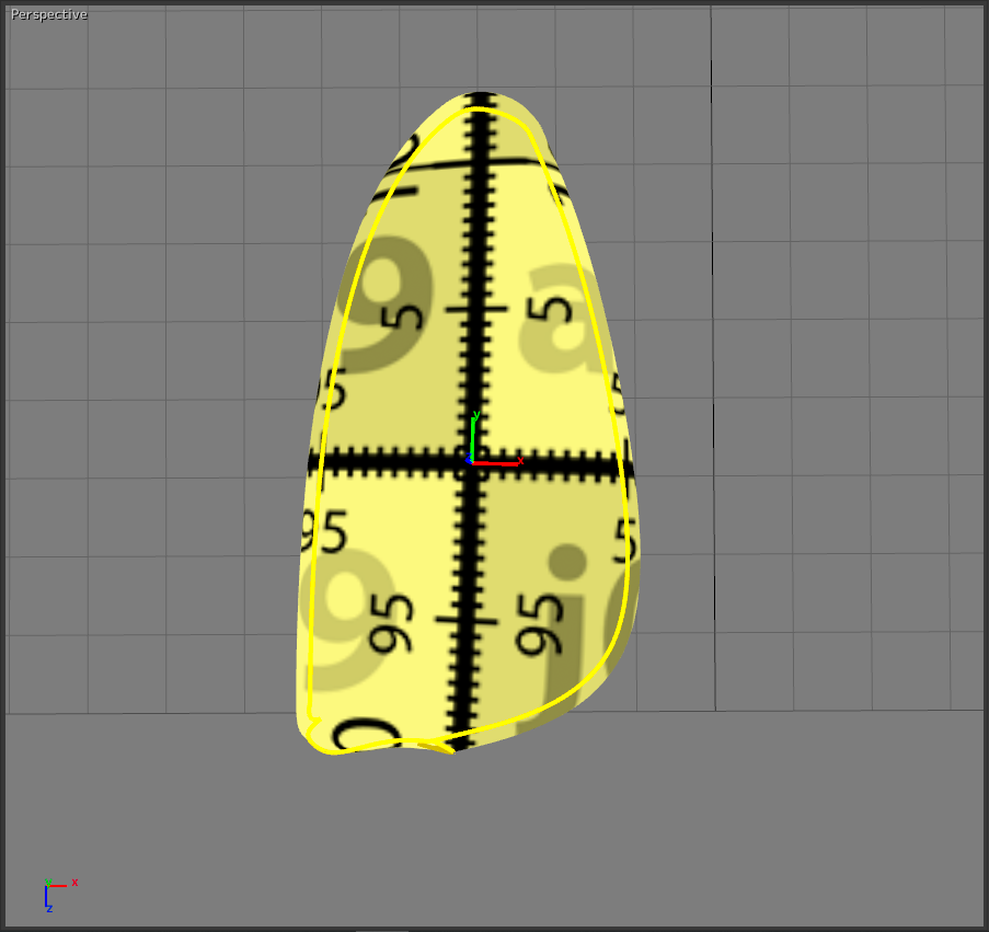
In this 3D view, the control points are marked in green and the delimited cutting path is displayed in red.
Cut Properties Panel
The Cut Properties panel is divided into two boxes, the Preprocess box and the Cut Points box.
The Preprocess box provides access to three modes for preparing surfaces before defining a cutting path: None, Sew, Weld and Sew. The Cut Points box allows the user to keep track of the number of control points defined. The Cut! button performs a defined cut based upon control points.
Defining a Cutting Path
Preprocessing Boundaries
Depending on the surface topology, the user may wish to prepare before defining a cutting line. The preparation tools available in the Preprocess box of the Cut Properties panel are Sew and Weld and Sew. They have the same effects as the preprocess options in the Unfolding workshop.
Defining Control Points
Control points are set using the Quick Assignment mode in the 3D geometry toolbar. They may be placed on any triangle vertex. Control points define cutting path segments. Users need to set at least two control points and may set more.
To set a control point, users click on the matching vertex.
Control points are displayed in green. The cutting path segment defined by two control points is the shortest path between them. It is displayed in red.
Note
If a control point is behind the surface from the user’s standpoint, the green dot will not be visible.
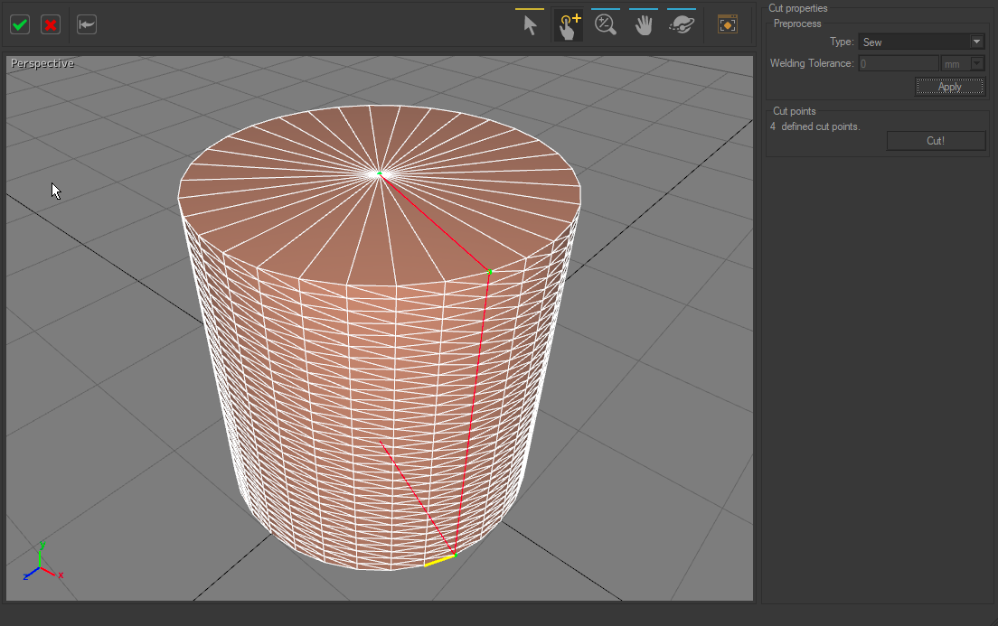
A cutting path defined by four control points: the cutting path is displayed in red and the control points in green.
Modifying Existing Control Points
The Select and Move tool is for dragging any of the points belonging to the red line, control points included, and assigning them to another triangle vertex.
Right-clicking on a control point opens a box containing three options. The user may then.
Delete current control point.
Continue to insert markers using the Insert New Marker After option. When this option is activated, the next triangle vertex selected becomes a control point.
Delete All Markers.
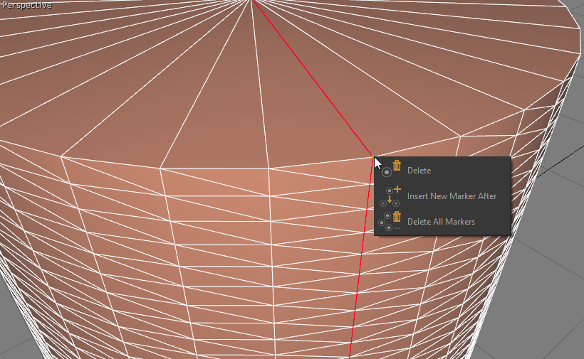
The three options available when right-clicking on a marker.
Applying the Cutting Path
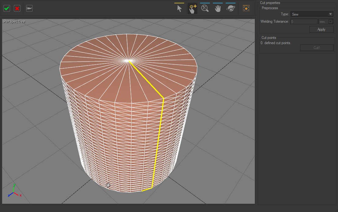
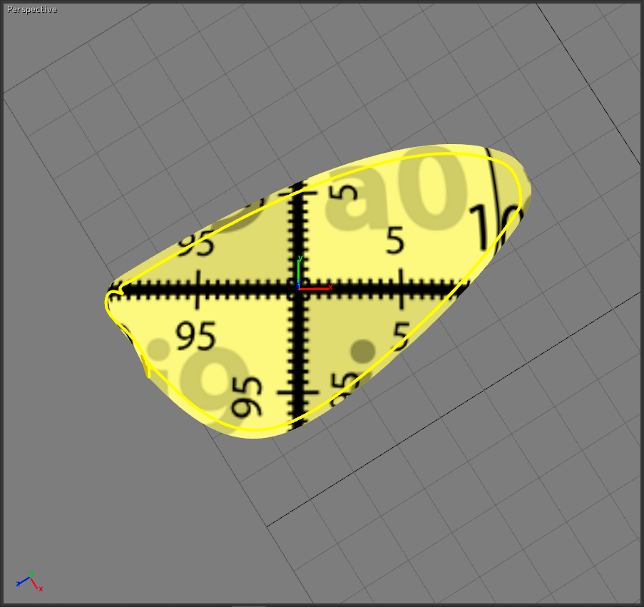
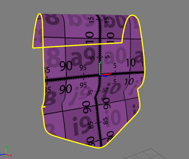
The final cutting path is displayed in yellow. No markers exist any longer.
Once the cut path is defined, cutting is performed by pressing the Cut! button. It is displayed in yellow afterward. Users may define additional cutting paths if needed.
In order to unfold a surface, users validate the cut from the validation commands toolbar and return to the unfolding workshop to get the proper UV-mapping of the surface.
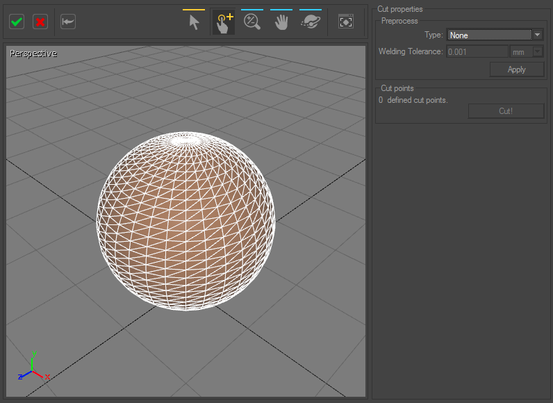
In the case of a sphere, the surface cannot be unfolded onto a plane without being cut in places: use of the surface cutting workshop is recommended.
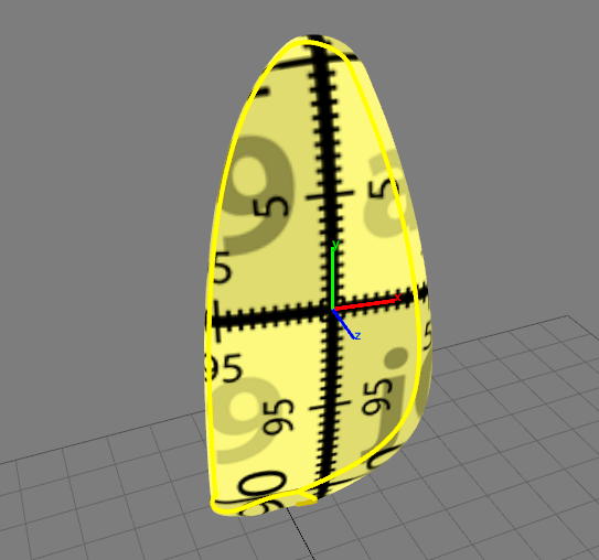
UV-mapping obtained when defining a cutting path in the surface cutting workshop.
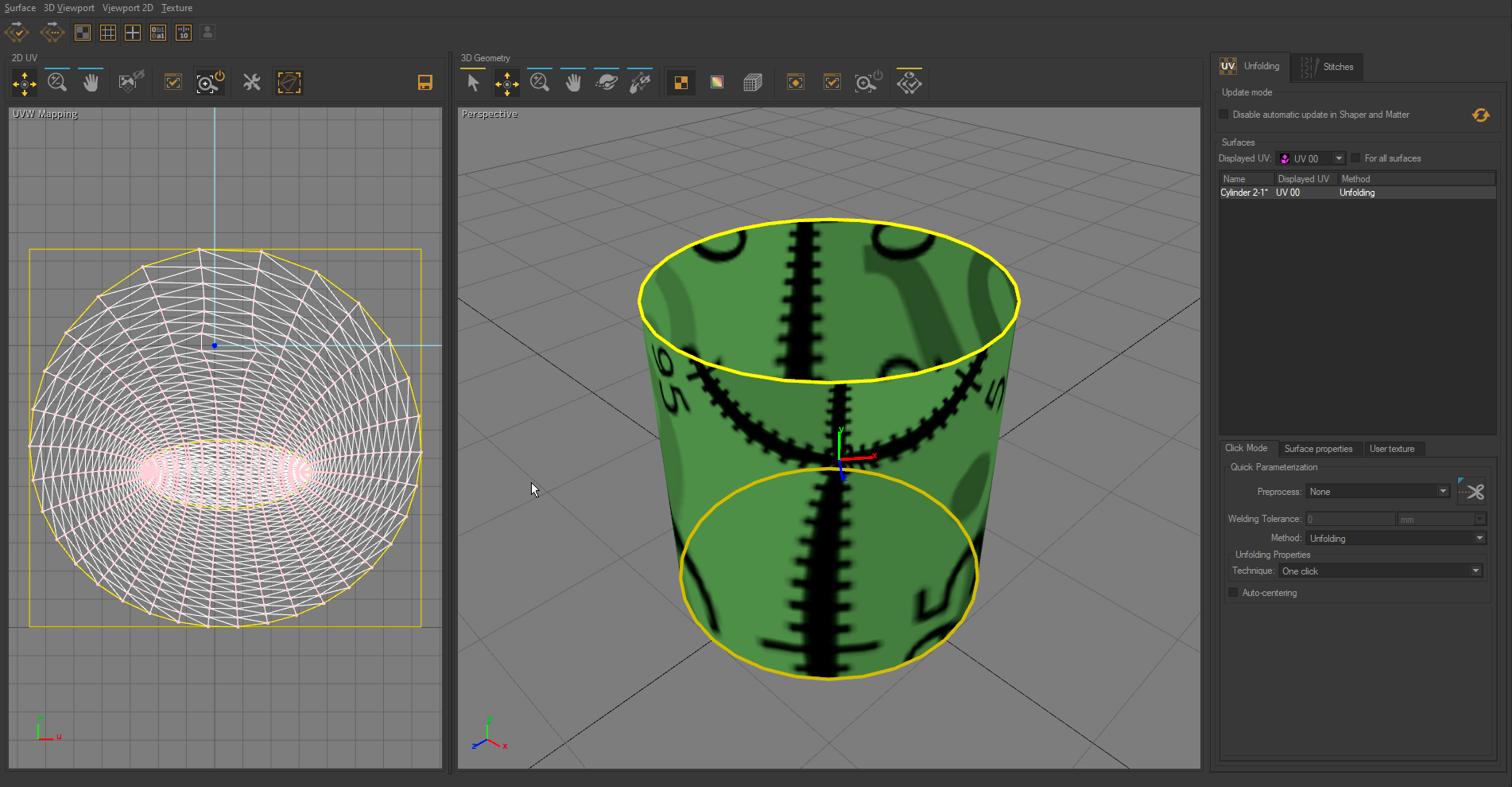
UV-mapping obtained without using the surface cutting workshop.